Distributed optical fiber gas detecting device and method based on sweep frequency technology

A distributed optical fiber and gas detection technology, applied in the measurement of color/spectral characteristics, etc., can solve the problems of not being called a distributed optical fiber gas sensor, unable to measure multiple parameters of optical fiber gas at the same time, and difficult to achieve the results. High precision, simple structure, effect of eliminating influence

Pending Publication Date: 2019-11-08
YANCHENG INST OF TECH
View PDF4 Cites 2 Cited by
  • Summary
  • Abstract
  • Description
  • Claims
  • Application Information

AI Technical Summary

Problems solved by technology

Judging from these reports, these inventions are point-type optical fiber gas sensors, which cannot be called distributed optical fiber gas sensors, and cannot simultaneously realize the measurement of multiple gas parameters along the optical fiber, so it is difficult to implement industrialization

Method used


Image

  • Distributed optical fiber gas detecting device and method based on sweep frequency technology
  • Distributed optical fiber gas detecting device and method based on sweep frequency technology
  • Distributed optical fiber gas detecting device and method based on sweep frequency technology

Examples


Embodiment Construction

[0025] Below in conjunction with accompanying drawing and specific embodiment, further illustrate the present invention, should be understood that these examples are only for illustrating the present invention and are not intended to limit the scope of the present invention, after having read the present invention, those skilled in the art will understand various aspects of the present invention All modifications of the valence form fall within the scope defined by the appended claims of the present application.

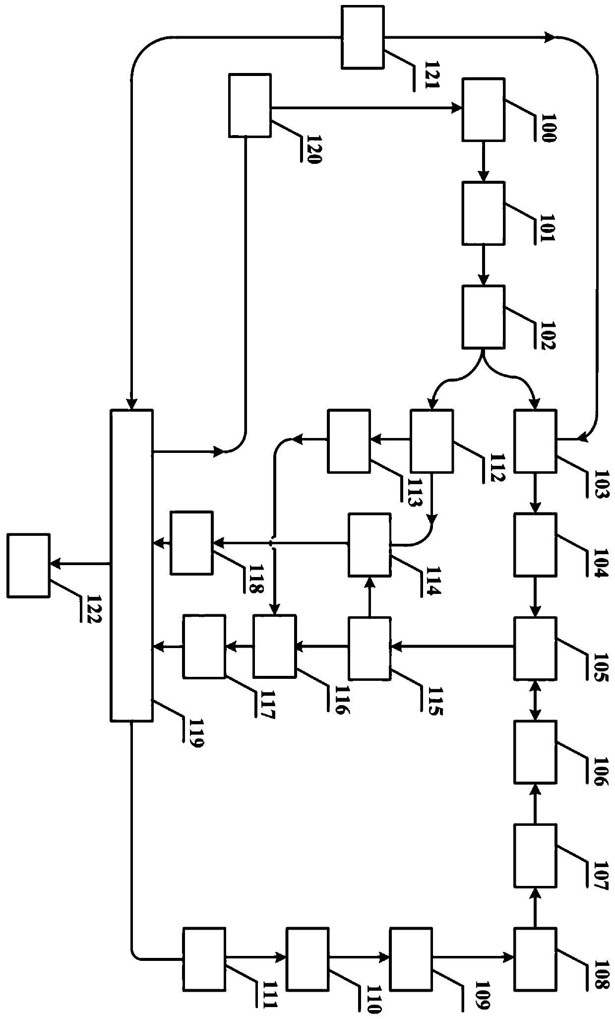
[0026] A distributed optical fiber gas detection device based on frequency sweep technology, such as figure 1 As shown, it includes a first laser 100, a first isolator 101, a first coupler 102, an acousto-optic modulator 103, a first erbium-doped fiber amplifier 104, a circulator 105, a sensing fiber 106, a second erbium-doped fiber amplifier 107, second isolator 108, second laser 109, laser controller 110, lock-in amplifier 111, second coupler 112, polarization scra...


PUM

PropertyMeasurementUnit
diameteraaaaaaaaaa

Abstract

The invention discloses a distributed optical fiber gas detecting device and method based on a sweep frequency technology. The device comprises a first laser, a first isolator, a first coupler, an acousto-optic modulator, a sensing fiber, a second erbium-doped fiber amplifier, a second laser, a second coupler, a scrambler, a third coupler, a fourth coupler, a fifth coupler, a first photoelectric detector, a second photoelectric detector, and a pulse generator. With the sweep frequency technology, each detection point on the sensing fiber is scanned by multiple times to realize effective suppression of a dead zone. A detection pulse signal generates a back-scattered Rayleigh scattering signal in the sensing fiber; and phase information of the reflected Rayleigh scattering signal is detectedto obtain concentration and composition information of the gas along the sensing fiber is obtained. The method is simple; the high-precision gas concentration information detection can be realized; and the detection of different gas has high applicability.

Description

technical field [0001] The invention relates to a gas detection device and method, in particular to a device and method for continuous distributed optical fiber gas detection. Background technique [0002] The rapid development of my country's economy has brought serious safety problems. Frequent occurrences of various types of vicious accidents have not only caused personal injury to relevant practitioners, but also caused huge economic losses to the country and had a bad social impact. These accidents are basically related to the rapid detection of dangerous gases, real-time monitoring and other related issues. In addition, environmental problems have become increasingly prominent in recent years. The greenhouse effect, acid rain, smog and other phenomena caused by air pollution have not only caused direct or indirect economic losses to society, but also caused serious harm to people's health. Optical fiber sensing technology is a new type of sensing technology that uses ...

Claims


Application Information

Patent Timeline
Patent Type & Authority Applications(China)
IPC IPC(8): G01N21/39
CPCG01N21/39
Inventor 徐东超周锋王新宇戚志澳祁欣玥王如刚
Owner YANCHENG INST OF TECH
Why Eureka
Try Eureka