Volatile organic chemicals (VOCs) recovery system based on liquefied natural gas (LNG) cold energy

A recovery system and cold energy technology, applied in pipeline systems, container discharge methods, and equipment discharged from non-pressure containers, etc., can solve problems such as affecting normal supply and VOCs emissions failing to meet requirements, and reduce equipment investment. Cost, Emission Reduction, and Recovery Efficiency

Inactive Publication Date: 2019-11-12
QINGDAO UNIV OF SCI & TECH
View PDF6 Cites 2 Cited by
  • Summary
  • Abstract
  • Description
  • Claims
  • Application Information

AI Technical Summary

Problems solved by technology

[0005] Patent CN 206488547U discloses a VOCs gas device that utilizes LNG cold energy to recover oil tank discharge, discharges LNG and VOCs gas into a heat exchanger, and directly utilizes LNG cold energy to condense and liquefy VOCs gas. Although this method realizes LNG cold energy However, since there is no adsorption process after the VOCs are condensed and recovered, the non-condensable gas is directly discharged into the air, which will cause the VOCs emission to fail to meet the requirements, and due to the direct heat exchange between LNG and VOCs gas, when the VOCs recovery system fails, it will Affect the normal supply of LNG

Method used


Image

  • Volatile organic chemicals (VOCs) recovery system based on liquefied natural gas (LNG) cold energy

Examples


Embodiment 1

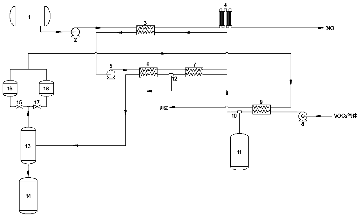
[0027] Such as figure 1 As shown, a VOCs recovery system based on LNG cold energy, including LNG cold energy supply system, VOCs condensation recovery system and VOCs adsorption purification system,

[0028] In this example, the VOCs gas concentration from the production link is 50g / m 3 , the temperature is 40°C, and the type is mixed aromatic hydrocarbons.

[0029] In the LNG cold energy supply system, after the LNG from the LNG storage tank (1) is pressurized by the LNG booster pump (2), it is vaporized into NG in the LNG heat exchanger (3), and the cold energy is transferred to VOCs condenses the R22 in the recovery system, the temperature of NG rises to -130°C, and then the temperature of NG rises to 25°C in the air-temperature vaporizer (4). After the R22 is cooled to -120°C in the LNG heat exchanger (3), after being pressurized by the refrigerant circulation pump (5), it enters the VOCs deep cooler (6) and the VOCs primary cooler (7) successively to release cold energy...

Embodiment 2

[0033] In this example, the VOCs gas temperature from the production link is consistent with the type and embodiment 1, and the concentration rises to 100g / m 3 .

[0034] In the LNG cold energy supply system, LNG is vaporized into NG in the LNG heat exchanger (3), and the cold energy is transferred to R22 in the VOCs condensation recovery system. Warming up to 25°C in the carburetor (4). After the R22 is cooled to -120°C in the LNG heat exchanger (3), it enters the VOCs cryocooler (6) and the VOCs primary cooler (7) in turn to condense the liquefied VOCs gas, and the VOCs cryocooler (6) exits The temperature of R22 rises to -113°C, and the temperature of R22 rises to -68°C at the outlet of the VOCs primary cooler (7).

[0035] In the VOCs condensation recovery system, the VOCs gas is cooled to -5°C in the VOCs dehydrator (9), the water vapor in the VOCs gas is removed, and the condensed water is discharged into the collector in the first pipeline separator (10). Water tank ...

Embodiment 3

[0038] In this example, the VOCs gas temperature from the production link is consistent with the type and embodiment 1, and the concentration rises to 150g / m 3 .

[0039] In the LNG cold energy supply system, LNG is vaporized into NG in the LNG heat exchanger (3), and the cold energy is transferred to R22 in the VOCs condensation recovery system. Warming up to 25°C in the carburetor (4). After the R22 is cooled to -120°C in the LNG heat exchanger (3), it enters the VOCs cryocooler (6) and the VOCs primary cooler (7) in turn to condense the liquefied VOCs gas, and the VOCs cryocooler (6) exits The temperature of R22 rises to -110°C, and the temperature of R22 rises to -65°C at the outlet of the VOCs primary cooler (7).

[0040] In the VOCs condensation recovery system, the VOCs gas is cooled to -5°C in the VOCs dehydrator (9), the water vapor in the VOCs gas is removed, and the condensed water is discharged into the collector in the first pipeline separator (10). Water tank ...


PUM


Abstract

The invention provides a volatile organic chemicals (VOCs) recovery system based on liquefied natural gas (LNG) cold energy. The VOCs recovery system based on the LNG cold energy comprises an LNG coldenergy supply system, a VOCs condensation and recovery system and a VOCs adsorption and purification system. In an LNG heat exchanger, LNG utilizes a middle refrigerant for transmitting the cold energy to a VOCs primary cooler and a VOCs chelloller, VOCs gas is condensed and liquified, the residual VOCs gas is purified in an adsorption tank, and then water vapor in the VOCs can be removed by utilizing the residual cold energy in the VOCs gas in a VOCs dehydrater. According to the VOCs recovery system based on the LNG cold energy provided by the invention, the LNG is used as a cold source, andthe utilization on the LNG cold energy is realized through the middle refrigerant, so that the utilization ratio of the LNG energy is improved, meanwhile, an LNG supply process and a VOCs recovery process are separated, the VOCs condensation and recovery system and the adsorption and purification system are effectively prevented from influencing the normal supply of the LNG when going wrong, andthe safety of the system is improved; and in addition, compared with a traditional VOCs recovery method, according to the VOCs recovery system based on the LNG cold energy provided by the invention, acondensation method and an adsorption method are combined, so that the VOCs recovery efficiency is greatly improved.

Description

technical field [0001] The invention relates to the field of VOCs recovery, in particular to a VOCs recovery system based on LNG cold energy. Background technique [0002] Volatile Organic Compounds (Volatile Organic Compounds, VOCs) is a general term for a series of volatile, flammable and toxic organic compounds. It is an important cause of smog and PM2.5. , It is necessary to strengthen the recovery and management of VOCs. [0003] At present, the conventional technologies for oil and gas recovery in domestic petroleum industry mainly include adsorption method, absorption method, membrane separation method, condensation method and so on. Among them, the adsorption method has large losses and high operating costs; the absorption method takes up a lot of space, high energy consumption, and exhaust emissions are difficult to meet the standards; the membrane separation method has a large load and high investment; the condensation method is affected by refrigerants, refrigera...

Claims


Application Information

Patent Timeline
Patent Type & Authority Applications(China)
IPC IPC(8): F17D1/02F17D3/14F17C9/02B01D53/00B01D53/04
CPCB01D53/002B01D53/04B01D2257/708F17C9/02F17C2221/033F17D1/02F17D3/145Y02A50/20
Inventor 胡德栋杨桑宇孙国靖宋天舒孙子贻
Owner QINGDAO UNIV OF SCI & TECH
Why Eureka
Try Eureka