Gas density monitoring device for realizing maintenance-free of density relay, system and method

A technology of density relay and gas density, which is applied in the field of electric power, and can solve problems such as the reduction of insulation strength on the surface of insulating parts, flashover, and hazards

Pending Publication Date: 2019-11-12
SHANGHAI ROYE ELECTRICAL CO LTD
View PDF0 Cites 1 Cited by
  • Summary
  • Abstract
  • Description
  • Claims
  • Application Information

AI Technical Summary

Problems solved by technology

3) When the temperature drops, too much moisture may form condensation water, which will significantly reduce the insulation strength of the surface of the insulating part, or even flashover, causing serious damage
In addition, if the on-site inspection of the inspectors is not performed in a standardized manner, there are still potential safety hazards

Method used


Image

  • Gas density monitoring device for realizing maintenance-free of density relay, system and method
  • Gas density monitoring device for realizing maintenance-free of density relay, system and method
  • Gas density monitoring device for realizing maintenance-free of density relay, system and method

Examples


Embodiment 1

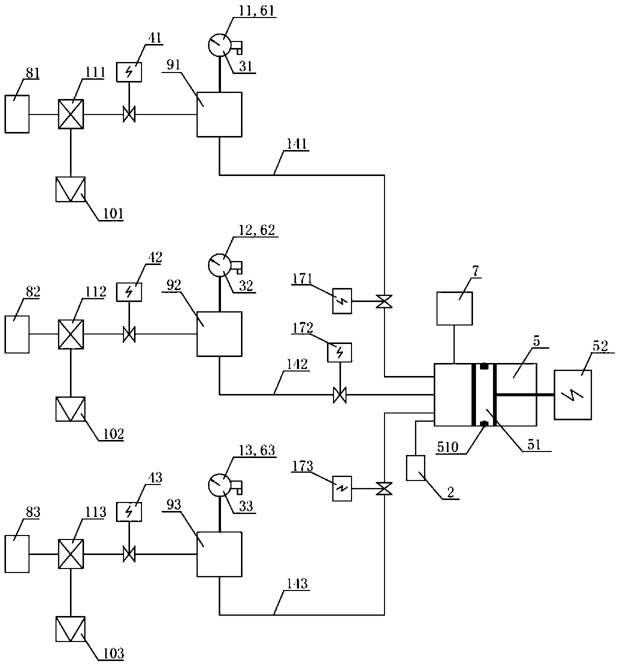
[0147] Such as figure 1 As shown, a gas density monitoring device that realizes maintenance-free density relays includes: a pressure regulating mechanism 5, an intelligent control unit 7, and a pressure sensor 2, and the pressure sensor 2 is connected to the pressure regulating mechanism 5 on an air circuit. The gas path of the pressure regulating mechanism 5 is divided into three branches through connecting pipes, namely a first branch 141 , a second branch 142 and a third branch 143 . Each branch is equipped with a pre-valve, a multi-way joint, a post-valve, a temperature sensor and an on-line verification contact signal sampling unit. Among them, one end of each pre-valve is provided with an interface connected with its corresponding electrical equipment, and the other end of the pre-valve is connected with the gas path of the corresponding gas density relay through a multi-way joint; one end of each post-valve The gas path of the corresponding gas density relay is connect...

Embodiment 2

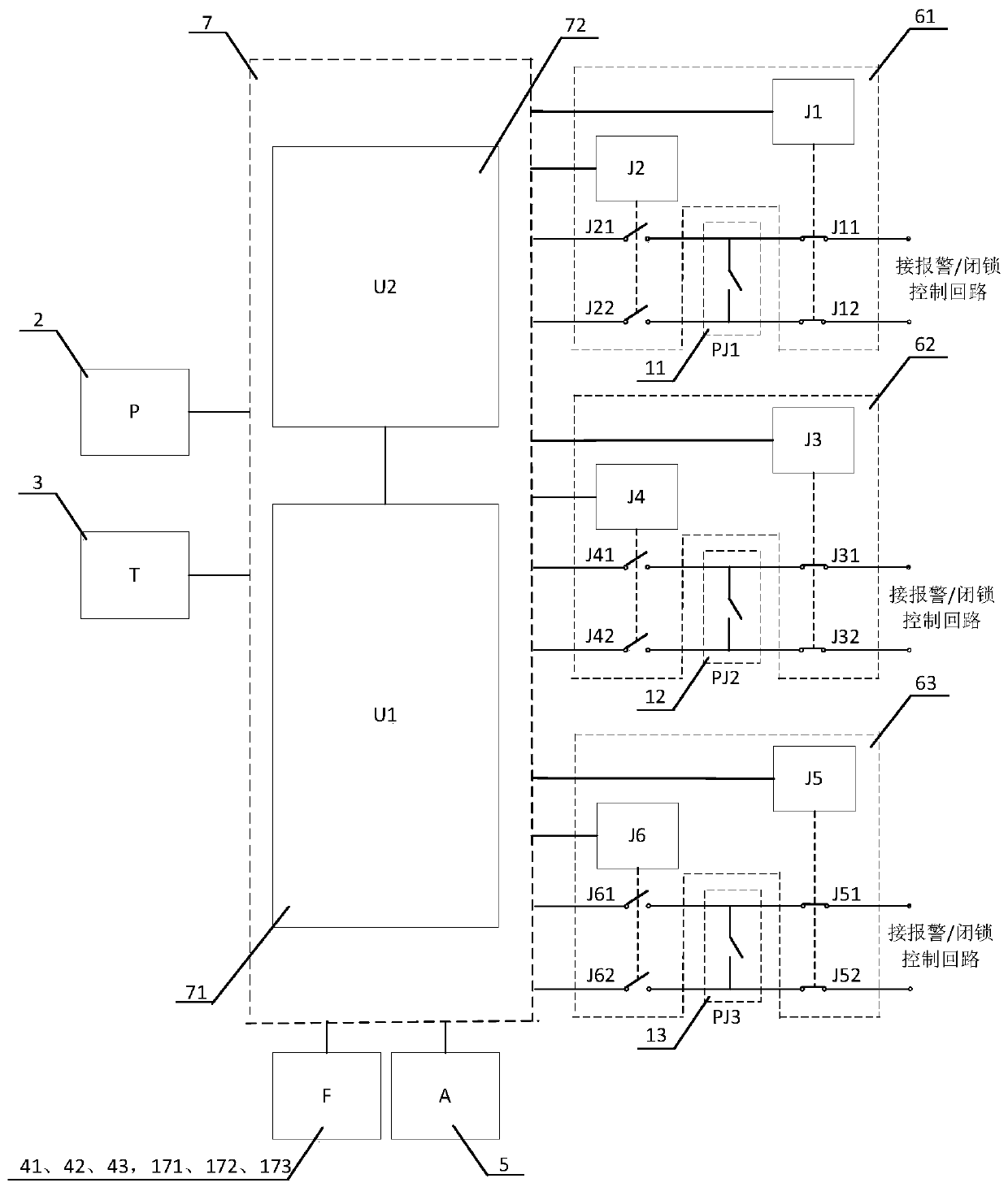
[0158] figure 2 It is a schematic diagram of the control circuit of a gas density monitoring device. Such as figure 2 As shown, the gas path of the pressure regulating mechanism 5 is connected with three branches, and each branch is provided with an online verification contact signal sampling unit, which has the same structure, and is respectively an online verification contact signal sampling unit 61, an online verification Contact signal sampling unit 62 and online verification contact signal sampling unit 63, the online verification contact signal sampling unit on each branch is provided with a sampling contact connected to the gas density relay on the branch, configured to sample the gas The contact signal of the density relay and the online verification contact signal sampling unit on each branch are also connected with the intelligent control unit 7 .

[0159] The basic requirements or functions of the online verification contact signal sampling unit on each branch a...

Embodiment 3

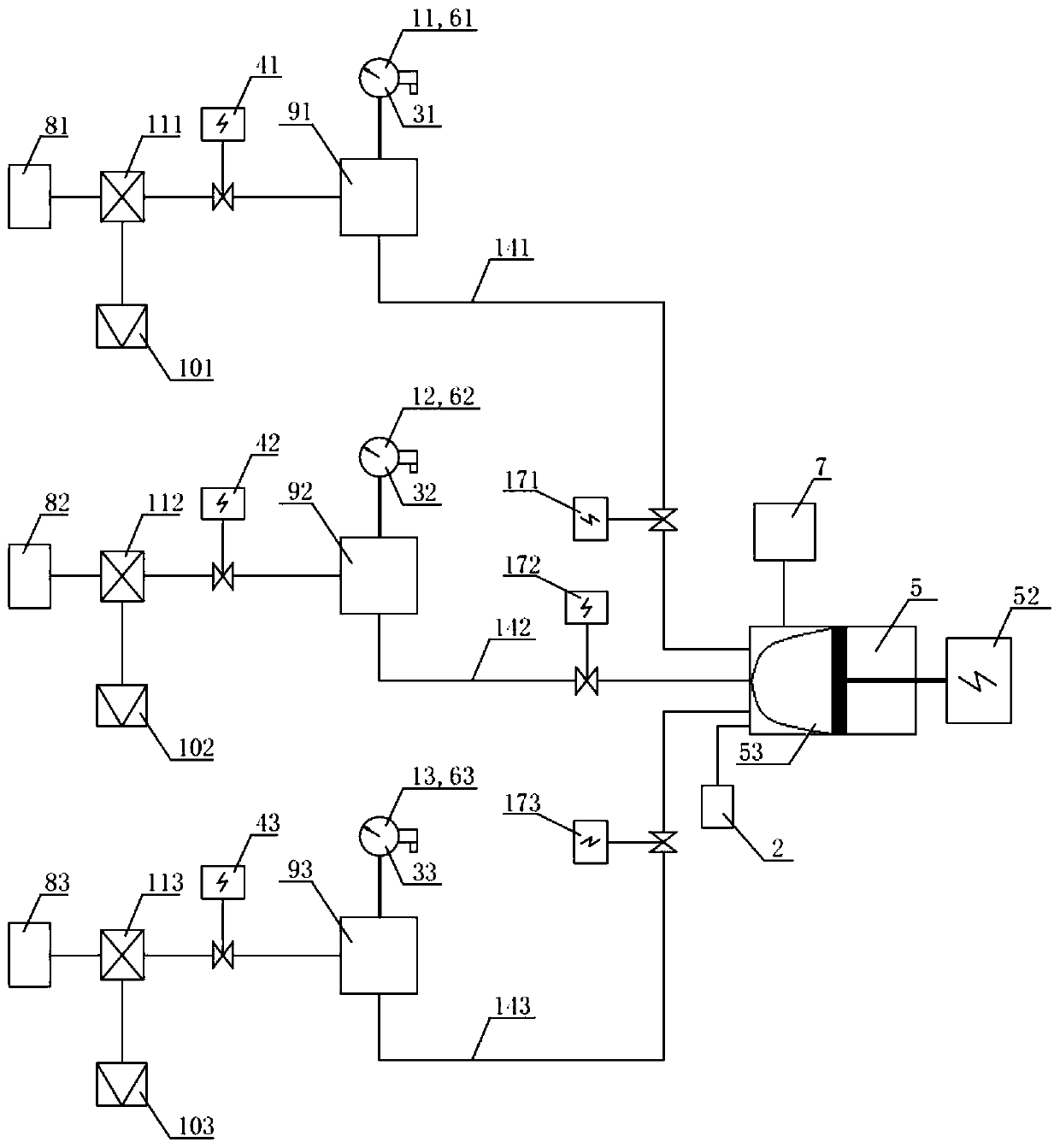
[0178] Such as image 3 As shown, the difference between the gas density monitoring device of this embodiment and Embodiment 1 is:

[0179] The pressure regulating mechanism 5 of this embodiment is mainly composed of an air bag 53 and a driving part 52 . According to the control of the intelligent control unit 7 , the pressure regulating mechanism 5 makes the driving part 52 push the air bag 53 to change in volume, and then complete the pressure rise and fall. The pressure is regulated by the pressure regulating mechanism 5, so that the gas density relay on the branch takes a contact action, and the contact action is transmitted to the intelligent control unit 7 through the online verification contact signal sampling unit on the corresponding branch. The pressure value and temperature value when the contact action of the gas density relay is converted into the corresponding density value, and the contact action value and / or return value of the gas density relay on the corresp...


PUM


Abstract

The application provides a gas density monitoring device for realizing maintenance-free of a gas density relay, and the device comprises at least one pressure regulating mechanism, at least one gas detecting sensor and at least one intelligent control unit, wherein the pressure regulating mechanisms are connected with at least one branch on the gas paths, and each branch is provided with a front valve. The pressure fluctuation of the pressure regulating mechanism is controlled by the intelligent control units to complete the on-site monitoring of the gas density relay, with no maintenance personnel required for on-site operation, thereby realizing the maintenance-free of the gas density relay and greatly improving the efficiency and reliable and safe operation of the grid. The applicationalso provides a gas density monitoring system including the above gas density monitoring device, and provides a gas density monitoring method that supports the normal operation of the above gas density monitoring device.

Description

technical field [0001] The invention relates to the field of electric power technology, in particular to a gas density monitoring device, system and method that are applied to high-voltage electrical equipment and realize maintenance-free density relays. Background technique [0002] Gas density relay is generally used to monitor and control the density of insulating gas in high-voltage and medium-voltage electrical equipment. It is equipped with a contact signal control circuit inside. When a gas leak occurs, the contact of the gas density relay will act to generate a contact signal, and the contact signal control circuit will send an alarm or block according to the contact signal, so as to realize the safe operation protection of electrical equipment. [0003] At present, SF6 (sulfur hexafluoride) electrical equipment has been widely used in the power sector and industrial and mining enterprises, which has promoted the rapid development of the power industry. In recent ye...

Claims


Application Information

Patent Timeline
Patent Type & Authority Applications(China)
IPC IPC(8): G01N9/00G01D21/02
CPCG01D21/02G01N9/00
Inventor 贺兵常敏廖海明王乐乐曾伟蒲东海
Owner SHANGHAI ROYE ELECTRICAL CO LTD
Why Eureka
Try Eureka