
Impact over-current testing device

A test device, a technology of inrush current, applied in the direction of measuring device, measuring electricity, measuring electrical variables, etc., to achieve the effect of improving reliability and reducing power consumption

Inactive Publication Date: 2019-11-12
黑龙江省电工仪器仪表工程技术研究中心有限公司
View PDF6 Cites 0 Cited by
  • Summary
  • Abstract
  • Description
  • Claims
  • Application Information

AI Technical Summary

Problems solved by technology

[0004] The present invention aims to solve the problem that a single device cannot perform two tests of impulse current and overcurrent at the same time in the impact test of the impact overcurrent of the smart electric energy meter

Method used


Image

  • Impact over-current testing device

Examples


specific Embodiment approach 1

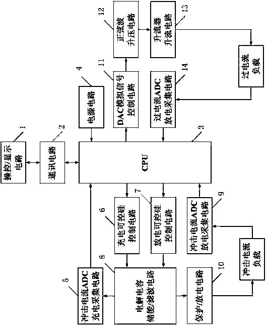
[0011] Specific implementation mode one: the following combination figure 1 Describe this embodiment, the impulse overcurrent test device described in this embodiment includes a control / display circuit 1, a communication circuit 2, a CPU 3, a power supply circuit 4, an inrush current ADC charging acquisition circuit 5, and a charging thyristor control circuit 6. Discharge thyristor control circuit 7. Electrolytic capacitor energy storage / filter circuit 8. Impulse current ADC discharge acquisition circuit 9. Protection / discharge circuit 10. DAC analog signal control circuit 11. Sine wave boost circuit 12. Current booster Up-current circuit 13, overcurrent ADC discharge acquisition circuit 14;

[0012] The control signal output end of the control / display circuit 1 is connected to the control signal input end of the communication circuit 2, the display signal input end of the control / display circuit 1 is connected to the display signal output end of the communication circuit 2, a...

specific Embodiment approach 2

[0017] Embodiment 2: This embodiment further limits the impact overcurrent test device described in Embodiment 1. In this embodiment, the impact current in the electrolytic capacitor energy storage / filter circuit 8 is greater than 600A and less than 6000A, and the current is increased. The overcurrent in the current booster circuit 13 is greater than 24A and less than 200A.

specific Embodiment approach 3

[0018] Embodiment 3: This embodiment further limits the impact overcurrent test device described in Embodiment 1. In this embodiment, the control / display circuit 1 is used to set parameters such as test current, number of tests, and test time, and Used to display impulse current and overcurrent test results and discharge waveforms.


PUM


Abstract

The invention discloses an impact over-current testing device, which solves the technical problem that the conventional impact current test and over-current test cannot be integrated into one device.An impact current main circuit adopts the R-L-C charging and discharging principle, and applies the pulse width modulation closed-loop feedback technology to generate a required impact current; and anover-current main circuit adopts the closed-loop up-current detection and control principle, which can automatically identify and calibrate different loads, so as to generate the required over-current. The impact current test and the over-current test are processed through an embedded ARM system, the ADC sampling feedback and a logic algorithm, and the impact current waveform and the over-currentwaveform are output according to the preset time and number of times. The impact over-current testing device is designed according to the short-time over-current influence test of GB / T 17215.321-2008as the leading; and the test main circuit is based on the theory of electromagnetic compatibility and adopts measures of special shielding, grounding, isolation and the like. The impact over-currenttesting device is applied to the field of impact current and over-current tests.

Description

technical field [0001] The invention relates to the field of impulse overcurrent test. Background technique [0002] With the continuous development and improvement of structural design ideas and methods, as well as the continuous application of high technology, the application problems encountered in the short-term overcurrent impact test of smart energy meters have attracted much attention. [0003] At present, the technical difficulties of the impulse current test and overcurrent test in China are not only the inability to integrate two similar tests into one device in the circuit structure, but also the insufficient protection measures, but also the low accuracy of the test current output and the integrity of the output waveform. The test stability, test time and frequency and other technical requirements are also lack of good response. Contents of the invention [0004] The invention aims to solve the problem that a single device cannot perform two tests of impulse c...

Claims


Application Information

Patent Timeline
Patent Type & Authority Applications(China)
IPC IPC(8): G01R35/04G01R1/28
CPCG01R1/28G01R35/04
Inventor 李超赵斌杨扬任美辉高红岩韩国刚徐军张迪史政
Owner 黑龙江省电工仪器仪表工程技术研究中心有限公司
Learn More