
Proportional electromagnet

A proportional electromagnet and armature technology, which is applied in the field of low-speed diesel engine high-pressure common rail system components, can solve problems affecting the performance of the common rail fuel system, emissions, difficulty in ensuring the coaxiality of the inner hole of the guide sleeve, and affecting the size of the fuel injection. Achieve the effects of improving coaxiality and reliability, avoiding loose plugs, and improving efficiency

Inactive Publication Date: 2019-11-12
CHONGQING HONGJIANG MACHINERY
View PDF6 Cites 0 Cited by
  • Summary
  • Abstract
  • Description
  • Claims
  • Application Information

AI Technical Summary

Problems solved by technology

The performance index of the proportional electromagnet directly affects the pressure establishment of the common rail fuel, which indirectly affects the fuel injection volume, and then affects the performance and emission of the common rail fuel system.
[0004] The main structure of the proportional electromagnet includes plug, shell, guide sleeve, armature and coil, etc. The guide sleeve of the traditional proportional electromagnet is generally processed and welded in sections, and the magnetic isolation ring is welded in the middle. The processing technology is complicated, and the inner hole of the guide sleeve is the same. The axiality is difficult to guarantee, which leads to the phenomenon of sticking easily when the armature moves in the inner hole of the guide sleeve
At the same time, the electromagnet will generate heat when it is working. When it is applied to a low-speed diesel engine, the high-temperature working environment will cause difficulty in heat dissipation, and the coil is prone to aging or even fusing.

Method used


Image

  • Proportional electromagnet
  • Proportional electromagnet
  • Proportional electromagnet

Examples


Embodiment Construction

[0024] In order to further illustrate the technical solution of the present invention, the present invention will be described in detail below in conjunction with the accompanying drawings.

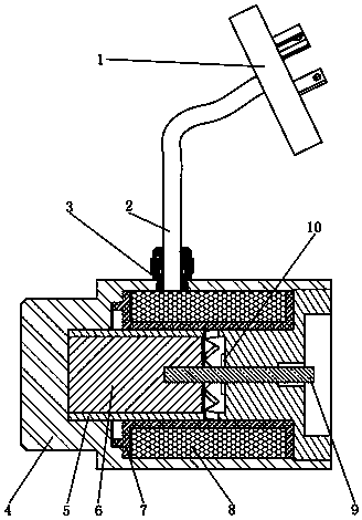
[0025] see figure 1 As shown, the proportional electromagnet for low-speed machines mainly includes a plug 1 , a casing 4 , a guide sleeve 5 , an armature 6 and a coil 8 .

[0026] The guide sleeve 5 is installed in the cavity of the housing, and the coil 8 is wound between the housing 4 and the guide sleeve 5 , the armature 6 is installed in the guide sleeve, and the front end of the armature 6 is equipped with a push rod 3 . The plug is connected to the power supply. When the power supply is energized, the current flows through the coil to generate a magnetic field, and the armature is magnetized to push the load forward; after the power is turned off, the electromagnetic force disappears, and the load pushes the armature back to zero. Within the effective stroke of the electromagnet, ...


PUM


Abstract

The invention discloses a proportional electromagnet for a low-speed motor, and the electromagnet comprises a plug, a shell, a guide sleeve, an armature and a coil. The guide sleeve is integrally machined and formed, wherein the rear section is a cavity for installing and containing the armature, the front section is a cylinder for a push rod to penetrate through to form a pole shoe, and a magnetic isolation hole is formed in the wall face, close to the pole shoe, of the rear section cavity. The guide sleeve is installed in a cavity of the shell, and the coil is arranged between the shell andthe guide sleeve. The armature is installed in the rear section cavity of the guide sleeve, the push rod is installed at the front end of the armature, and the push rod passes through the front section column body and extends out of the guide sleeve. According to the invention, when the proportional electromagnet is powered on to work, the armature reciprocates in the guide sleeve; the coaxialityof an inner hole of the guide sleeve is guaranteed due to the fact that the guide sleeve is integrally machined and formed, thereby guaranteeing that the armature cannot be clamped when moving in theinner hole of the guide sleeve; triangular grid hollows are formed in the wall surface of the guide sleeve, so that a linear magnetic isolation function of a traditional magnetic isolation ring structure is achieved, the process is simplified, and the reliability is improved.

Description

technical field [0001] The invention relates to a low-speed diesel engine high-pressure common rail system component, in particular to a proportional electromagnet. Background technique [0002] Compared with the traditional low-speed engine fuel injection system, the high-pressure common rail system for marine low-speed diesel engines has the advantages of adjustable injection pressure, adjustable fuel injection timing, and multiple injections. It is a key technology for realizing intelligent control of ships. [0003] The proportional electromagnet is one of the key components of the high-pressure common rail system of the low-speed machine. It is mainly used to control the actual amount of fuel inhaled by the pump unit during the oil suction stroke, so as to realize the control of the fuel pressure of the common rail pipe. The method of fuel pressure is the current mainstream control method. The performance index of the proportional electromagnet directly affects the pre...

Claims


Application Information

Patent Timeline
Patent Type & Authority Applications(China)
IPC IPC(8): H01F7/08H01F7/121H01F7/11H01F7/16
CPCH01F7/08H01F7/11H01F7/121H01F7/1607H01F2007/062H01F2007/1676
Inventor 商荣凯杨倩田梦江
Owner CHONGQING HONGJIANG MACHINERY
Learn More