
Composite material battery box

A technology of composite materials and battery boxes, which is applied in the direction of battery boxes/coats, secondary batteries, battery covers/end covers, etc., can solve problems such as poor insulation performance, weak corrosion resistance, and a large number of molds, and achieve mileage deviation Controllable, excellent shock and noise reduction performance, and the effect of improving safety performance

Pending Publication Date: 2019-11-15
TAIZHOU HUANGYAN SHUANGSHENG PLASTIC MOLD
View PDF0 Cites 9 Cited by
  • Summary
  • Abstract
  • Description
  • Claims
  • Application Information

AI Technical Summary

Problems solved by technology

Despite this optimization, the overall weight of the battery box is not well optimized
[0003] At the same time, the battery box made of sheet metal or aluminum alloy is limited by the material characteristics, has low design freedom, heavy weight, a large number of tooling and molds, high development costs, many parts processing procedures, weak corrosion resistance, and poor insulation performance. , poor shock absorption and noise reduction effects, especially the difficulty in controlling the balance of the internal temperature of the battery box, which makes the battery life vary greatly due to the influence of climate and region
In addition, considering the safety of the existing battery box, the material of the battery box must consider the problems of flame retardancy, heat dissipation and light weight, as well as the problem of spontaneous combustion of the vehicle battery charging, and the slow heat dissipation of the battery after driving a long-distance vehicle.
The battery lower case made of aluminum alloy, especially the upper cover part, has poor deformation resistance and is prone to plastic deformation under the condition of external impact

Method used


Image

  • Composite material battery box
  • Composite material battery box
  • Composite material battery box

Examples


Embodiment Construction

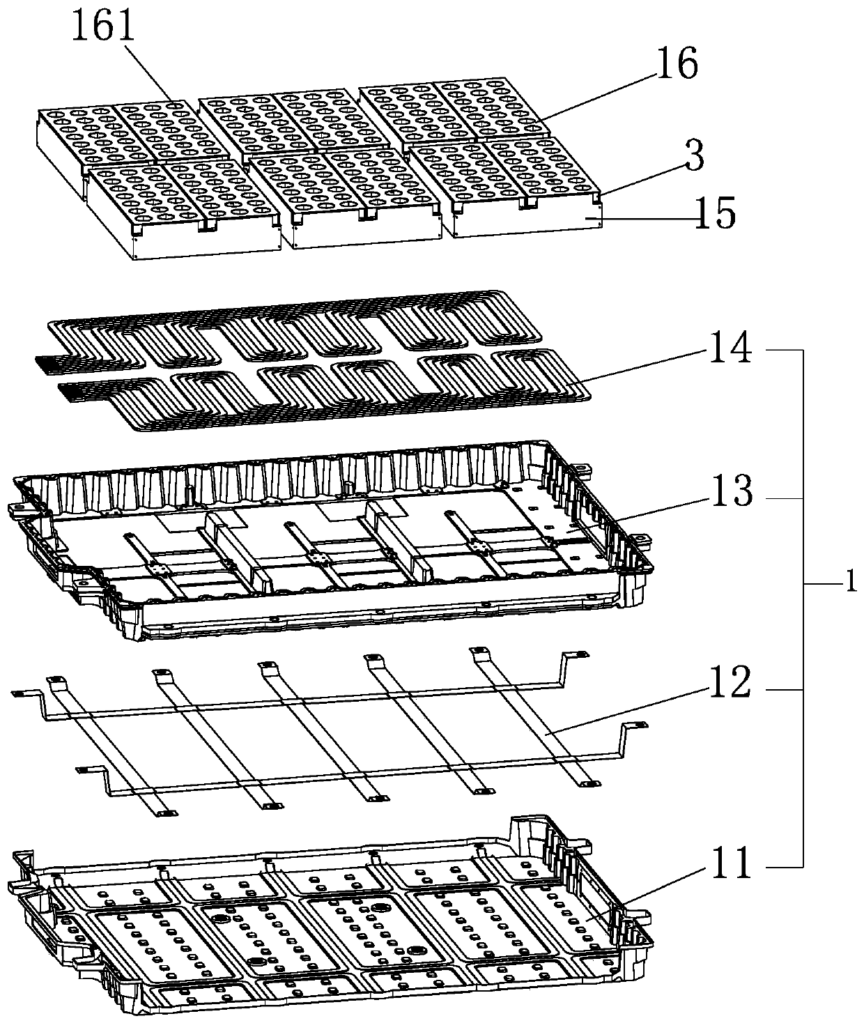
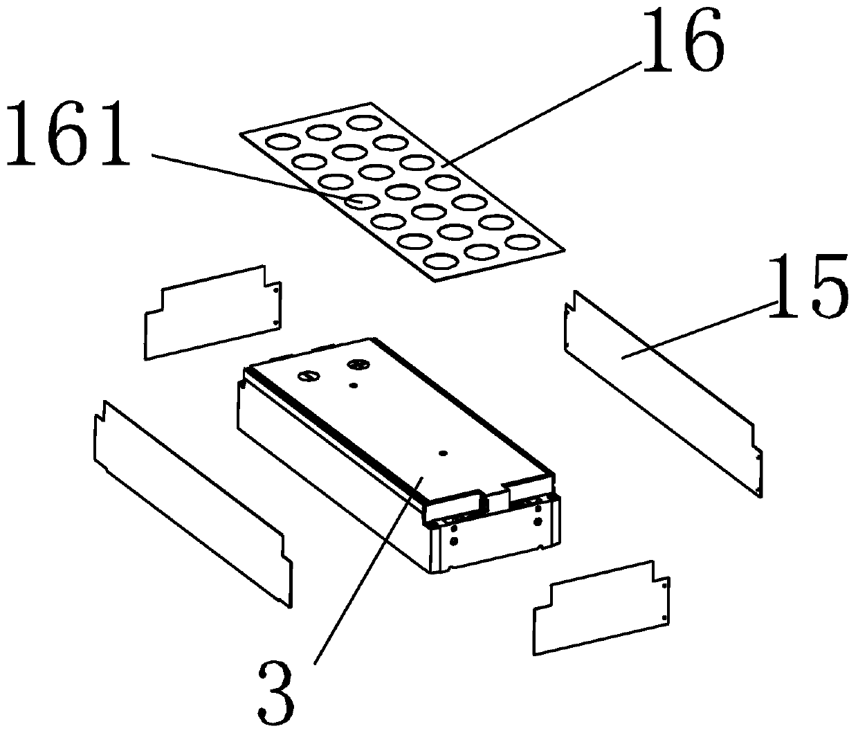
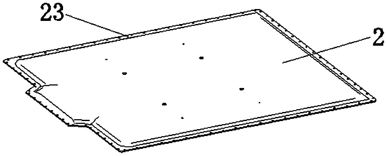
[0027] The present invention will be described in further detail below in conjunction with the accompanying drawings and embodiments.

[0028] like figure 1 and figure 2 As shown, a composite material battery case of the present invention includes a lower case 1 and an upper cover 2, and the lower case 1 and the upper cover 2 are connected by bolts on the outer periphery. The lower casing 1 is a sandwich sandwich structure, including an outer casing 11 , a reinforcing bracket 12 and an inner casing 13 bonded together by structural adhesive. In one embodiment, the outer shell 11 is formed by compression molding of high-strength continuous long glass fiber prepreg; the reinforcing bracket 12 is made of metal material, such as aluminum alloy or No. 20 cold-rolled steel plate; the inner shell 13 is made of short glass fiber The SMC material is molded, and the middle of the inner shell 13 and the outer shell 11 is a reinforcing bracket 12, and the three are bonded with structura...


PUM

PropertyMeasurementUnit
Thicknessaaaaaaaaaa
Thicknessaaaaaaaaaa
Thicknessaaaaaaaaaa

Abstract

The invention discloses a composite material battery box, which comprises a lower shell and an upper cover, wherein the lower shell is of a sandwich structure and comprises an outer shell, a reinforcing support and an inner shell which are bonded into a whole through a structural adhesive, a cooling water path layer is laid on the inner bottom surface of the lower shell, a plurality of battery packs are fixed on the cooling water path layer, and two adjacent battery packs are provide with a mica sheet therebetween; the upper cover is formed by compounding multiple layers of materials, the middle layer of the upper cover is a filling material layer, the upper surface and the lower surface of the filling material layer are laminated with a fiber material layer, and the filling material layerand the fiber material layer are adhered and fixed through foamed polyurethane sprayed on the fiber material layer. According to the technical scheme of the invention, the battery box formed by adopting the composite material of various different materials has the advantages of easy forming, good corrosion resistance, good insulation, high temperature resistance, heat insulation, flame retardance, explosion prevention and the like, improves the safety performance of the battery packs, improves the endurance mileage and the stability of the endurance mileage, reduces the mileage anxiety, and is excellent in shock absorption and noise reduction performance.

Description

technical field [0001] The invention relates to the technical field of battery boxes, in particular to a composite material battery box. Background technique [0002] There are more and more new energy vehicles, most of which are equipped with lithium iron phosphate batteries, but the battery box that can take into account the overall weight of the battery and the safety performance requirements has not been able to get a better solution, so many battery manufacturers and supporting OEMs We are constantly looking for new materials to replace the metal shell to reduce weight. In this case, the metal material is used as the bottom bracket and the glass fiber reinforced plastic material is used as the upper cover. The glass fiber reinforced plastic product has the advantages of light weight, high strength, flame retardancy, easy molding, and easy cleaning. To a certain effect. Despite such optimizations, the overall weight of the battery case is not well optimized. [0003] ...

Claims


Application Information

Patent Timeline
IPC IPC(8): H01M2/10H01M10/613H01M10/625H01M10/647H01M10/6556H01M10/6568H01M10/658H01M2/04B32B3/12B32B7/12B32B15/20B32B15/14B32B17/02B32B17/06B32B33/00
CPCH01M10/613H01M10/625H01M10/647H01M10/658H01M10/6556H01M10/6568B32B3/12B32B7/12B32B15/20B32B15/14B32B5/02B32B33/00B32B2457/10B32B2307/3065B32B2307/304B32B2307/718B32B2262/101H01M50/155H01M50/147H01M50/24H01M50/20Y02E60/10
Inventor 李加春王文双
Owner TAIZHOU HUANGYAN SHUANGSHENG PLASTIC MOLD
Learn More