Cooling system of self-baking electrode for brown corundum smelting in dump furnace

A self-baking electrode and cooling system technology, applied in electric heating devices, electrical components, heating by discharge, etc., can solve problems such as shortening the service life, and achieve the effect of improving the heat exchange effect.

Inactive Publication Date: 2019-11-15
重庆市赛特刚玉有限公司
View PDF5 Cites 0 Cited by
  • Summary
  • Abstract
  • Description
  • Claims
  • Application Information

AI Technical Summary

Problems solved by technology

[0004] The invention provides a self-baking electrode cooling system for smelting brown corundum in a dumping furnace to solve the problem in the prior art that the sheath and the annular tube are in a high-temperature environment for a long time, which reduces the service life

Method used


Image

  • Cooling system of self-baking electrode for brown corundum smelting in dump furnace
  • Cooling system of self-baking electrode for brown corundum smelting in dump furnace
  • Cooling system of self-baking electrode for brown corundum smelting in dump furnace

Examples


Embodiment 1

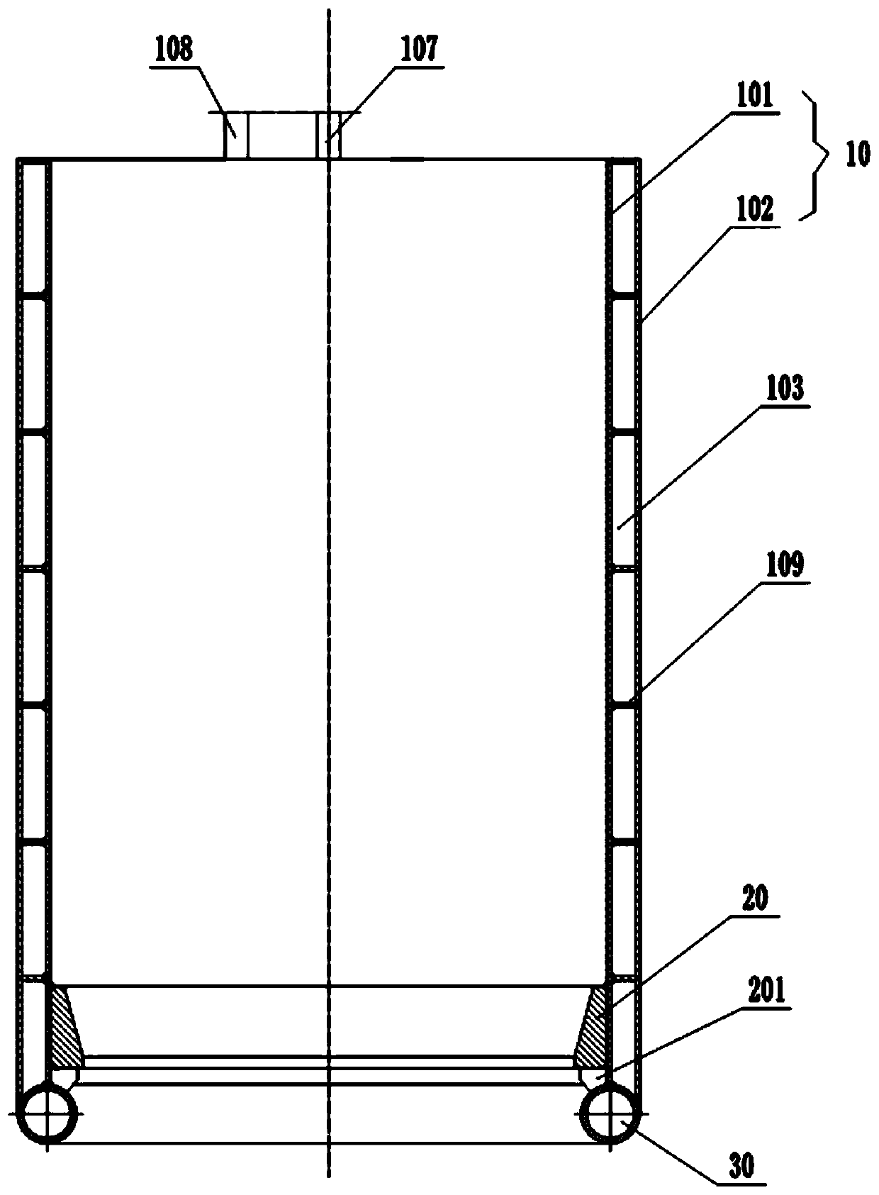
[0036] Embodiment 1 is basically as attached figure 1 and figure 2 Shown:

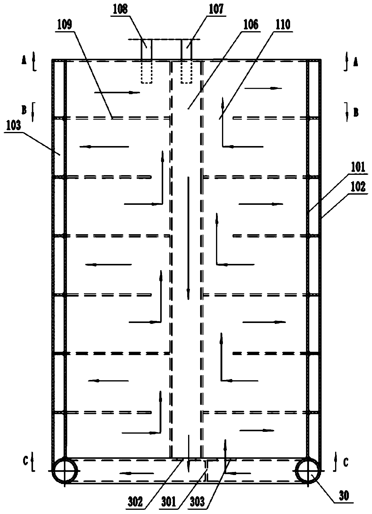
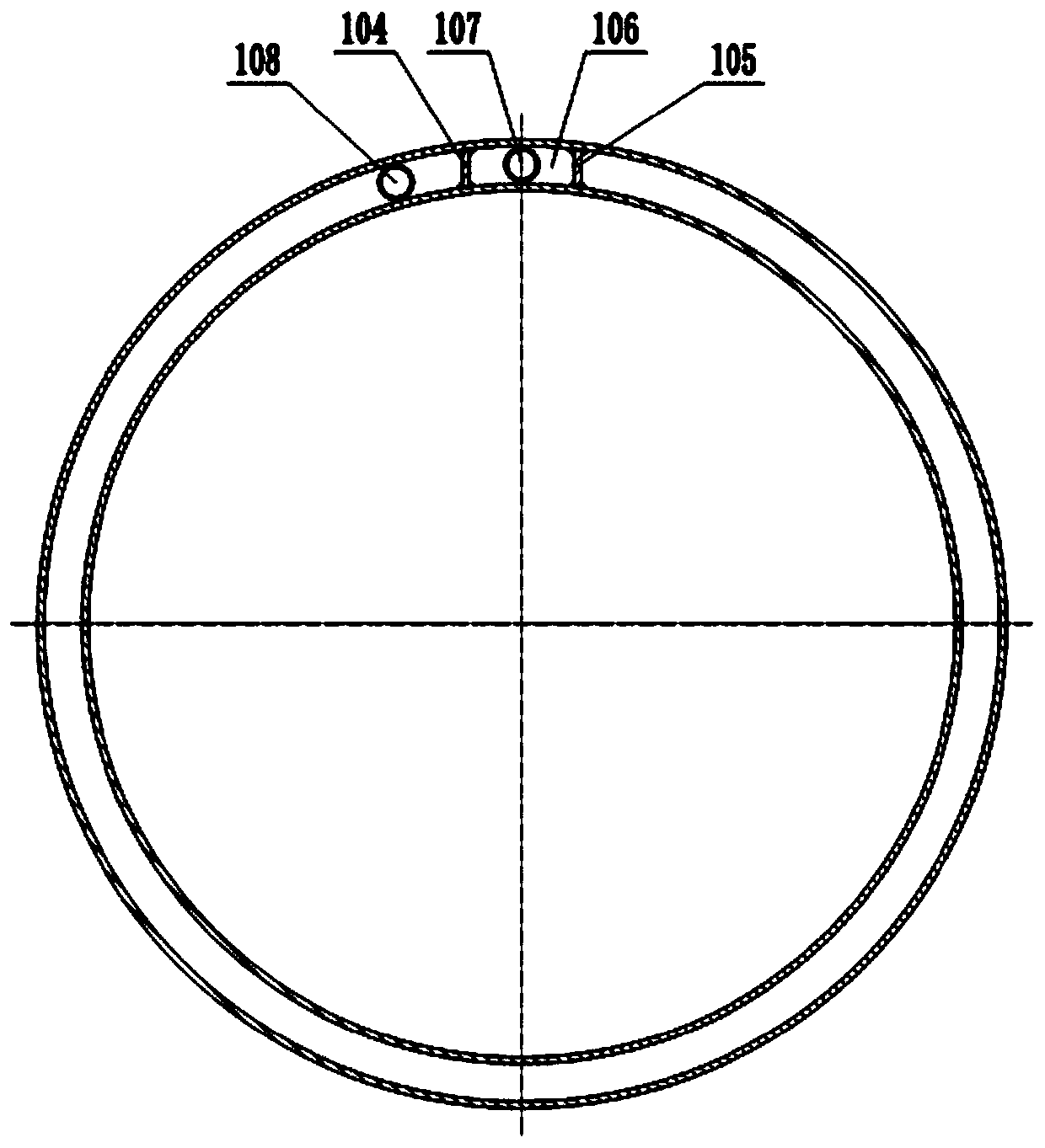
[0037] The self-baking electrode cooling system for smelting brown corundum in a dumping furnace includes a sheath 10, a tapered ring 20 and a hollow annular tube 30. The sheath 10 includes an inner layer 101 and an outer layer 102, and the annular tube 30 is welded to the inner layer At the bottom of the cover 101 and the outer cover 102, the tapered ring 20 is wide at the top and narrow at the bottom and is welded on the inner cover 101. Between the tapered ring 20 and the annular pipe 30, there is a connecting tapered ring 20, an annular The support plate 201 of the tube 30 and the inner layer cover 101, the inner layer cover 101, the outer layer cover 102 and the annular tube 30 form a closed cooling cavity 103, combined image 3 As shown, in the cooling cavity 103 along the axial direction of the sheath 10, a guard plate I 104 and a guard plate II 105 are welded, and a water inlet chamber 106 i...

Embodiment 2

[0043] Embodiment 2 is basically as Figure 6 Shown:

[0044] The difference from Embodiment 1 is that a deflector 40 is welded between both sides of the water deflector 301 and the inner wall of the annular pipe 30, and the upper surface of the deflector 40 on the right side of the water deflector 301 faces the water outlet 303, The upper surface of the deflector 40 on the left side of the water deflector 301 faces the water inlet 302, and the angle between the deflector 40 and the water deflector 301 is 20°-30°, and the included angle in this embodiment is 25° , in addition, the water inlet 302 and the water outlet 303 can all or partly be projected on the deflector 40 in the vertical direction.

[0045] Arranged like this, because when cooling water enters the annular pipe 30 through the water inlet 302, the water flow flowing to the water baffle 301 will form "retention" (that is, the flow velocity slows down), and the setting of the deflector 40 can allow the "delay" her...


PUM


Abstract

The invention relates to the technical field of smelting equipment, in particular to a cooling system of a self-baking electrode for brown corundum smelting in a dump furnace. The cooling system comprises a sheath, a cone-shaped ring and an annular pipe. The cone-shaped ring is fixed inside the sheath. The sheath consists of an inner sleeve and an outer sleeve. The bottom of the sheath is fixed together with the annular pipe. The inner sleeve, the outer sleeve and the annular pipe form a closed cooling cavity. The cooling cavity is internally provided with a water inlet cavity along the axialdirection of the sheath. A water inlet pipe communicated with the water inlet cavity and a water outlet pipe communicated with the cooling cavity are arranged on the top of the sheath. The annular pipe is provided with a water inlet communicated with the water inlet cavity and a water outlet communicated with the cooling cavity. The technical scheme of the invention solves the problem of short service life of the sheath and the annular pipe in the prior art due to the fact that the sheath and the annular pipe are in a high-temperature environment for a long time.

Description

technical field [0001] The invention relates to the technical field of smelting equipment, in particular to a cooling system for self-baking electrodes of brown corundum smelted in a dumping furnace. Background technique [0002] Self-baking electrodes use anthracite, coke, pitch and tar as raw materials to make electrode paste at a certain temperature, then put the electrode paste into the electrode shell installed on the electric furnace, and then sinter it into shape. This kind of electrode can be used continuously, and it can be sintered and formed while using it. Self-baking electrodes are widely used in brown corundum electric furnaces and calcium carbide furnaces because of their simple process and low cost. [0003] The external short grid is connected to the copper tile through a conductive copper tube and a water-cooled cable, and the current is applied to the electrode shell to bake the electrode paste, while the copper tile is limited and fixed through the outer...

Claims


Application Information

Patent Timeline
Patent Type & Authority Applications(China)
IPC IPC(8): H05B7/12
CPCH05B7/12
Inventor 谭华权邓延波匡孝福
Owner 重庆市赛特刚玉有限公司
Why Eureka
Try Eureka