Fabricated concrete gravity dam based on composite structure and construction method of fabricated concrete gravity dam

A concrete and prefabricated technology, applied in the direction of gravity dams, dams, water conservancy projects, etc., can solve the problems of long curing time of cast-in-place concrete, construction speed affected by the environment, high gravity dam temperature cracks, etc., to achieve easy quality control and construction Fast speed, reducing the effect of temperature cracks

Active Publication Date: 2019-11-19
KUNMING UNIV OF SCI & TECH
View PDF6 Cites 4 Cited by
  • Summary
  • Abstract
  • Description
  • Claims
  • Application Information

AI Technical Summary

Problems solved by technology

[0003] The purpose of the present invention is to solve the problems of strict temperature control and easy occurrence of temperature cracks in the construction of traditional gravity dams; long curing time is required for cast-in-place concrete, the construction speed is affected by the environment, and the dam building speed is low; the dam cannot be built in a short time. In order to achieve the function of water retaining or flood discharge, the cost of diversion is greatly increased, and a prefabricated concrete gravity dam based on a composite structure and its construction method are proposed.
This type of dam can make full use of the advantages of reliable quality and high construction efficiency of prefabricated concrete components and the advantages of good integrity and good seismic performance of cast-in-place concrete components, and fundamentally solve the problems of high-gravity dams that are prone to temperature cracks and low construction speed problems, providing a new approach for the construction of concrete gravity dams

Method used


Image

  • Fabricated concrete gravity dam based on composite structure and construction method of fabricated concrete gravity dam
  • Fabricated concrete gravity dam based on composite structure and construction method of fabricated concrete gravity dam
  • Fabricated concrete gravity dam based on composite structure and construction method of fabricated concrete gravity dam

Examples


Embodiment 1

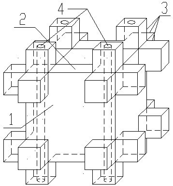
[0040] Embodiment 1: as Figure 1-8 As shown, a prefabricated concrete gravity dam based on a superimposed structure includes a superimposed structural concrete 11, an upstream concrete panel 12, a drainage grouting gallery 13, a downstream concrete panel 14, a plain concrete cushion 15, an anti-seepage curtain 16, Dam foundation drainage holes 17; the dam body is poured by superimposed structural concrete 11 except for the upstream concrete panel 12, drainage grouting corridor 13, downstream concrete panel 14, plain concrete cushion 15, anti-seepage curtain 16, and dam foundation drainage holes 17. (that is, the dam body is mainly composed of laminated structural concrete 11), the upstream concrete panel 12 and the downstream concrete panel 14 are poured on the upstream and downstream sides of the dam body;

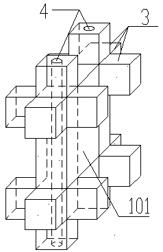
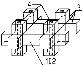
[0041] The composite structural concrete 11 includes a precast concrete member 1 and post-cast concrete 5 poured inside the precast concrete member 1 and between two adj...


PUM


Abstract

The invention relates to a fabricated concrete gravity dam based on a composite structure and a construction method of the fabricated concrete gravity dam, and belongs to the technical field of waterconservancy engineering. According to the fabricated concrete gravity dam, a dam body is mainly formed by pouring composite-structured concrete, and an upstream concrete panel and a downstream concrete panel are poured on the upstream side and the downstream side of the dam body; a plain concrete cushion is paved on a dam foundation, and the composite-structured concrete is laid on the plain concrete cushion; the composite-structured concrete is composed of precast concrete components and post-poured concrete in the precast concrete components, wherein the post-poured concrete is connected mutually to form a spatial frame structure system, and the stability of the dam body is enhanced; the advantages of the reliable quality of the precast concrete components, reduction of temperature cracks in the dam body and high construction efficiency can be fully used, meanwhile, due to the spatial frame structure system formed by the post-poured concrete, the integrity and stability of the dam body can be improved, and the safety of the dam body is ensured.

Description

technical field [0001] The invention relates to a prefabricated concrete gravity dam based on a superimposed structure and a construction method thereof, belonging to the technical field of water conservancy engineering. Background technique [0002] Traditional gravity dams are built by cast-in-place concrete. Since the cement emits a large amount of heat of hydration during the hydration process, it is easy to cause cracks in the concrete when there is a large temperature difference between the large-volume concrete and the external environment. , thus destroying the integrity of the concrete and affecting the safety of the dam. In order to prevent such temperature cracks, not only artificial cooling, cooling, heat dissipation and other measures must be taken during construction, but also block and layer pouring must be adopted. The interval between two layers of pouring needs 5~10 days or longer , thus seriously affecting the construction speed. Due to the limited const...

Claims


Application Information

Patent Timeline
Patent Type & Authority Applications(China)
IPC IPC(8): E02B7/10E02B3/12E02B3/14E02B3/16
CPCE02B3/129E02B3/14E02B3/16E02B7/10
Inventor 魏海魏成悦李文海吴华伟张国辉金格飞
Owner KUNMING UNIV OF SCI & TECH
Why Eureka
Try Eureka