Current detector based on metal-dielectric-metal waveguide

A detector and metal technology, applied in the field of current detection, can solve problems such as reducing the detection performance of the detector, and achieve the effects of small structure size, wide amplitude and high detection sensitivity

Inactive Publication Date: 2019-11-19
西安柯莱特信息科技有限公司
View PDF0 Cites 2 Cited by
  • Summary
  • Abstract
  • Description
  • Claims
  • Application Information

AI Technical Summary

Problems solved by technology

Most current detectors based on optical principles are based on optical fiber structure, and the birefringence effect of optical fiber material reduces the detection performance of this type of detector

Method used


Image

  • Current detector based on metal-dielectric-metal waveguide
  • Current detector based on metal-dielectric-metal waveguide
  • Current detector based on metal-dielectric-metal waveguide

Examples


Embodiment 1

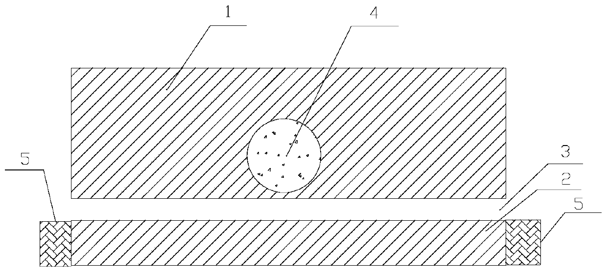
[0020] The present invention provides a figure 1 The current detector based on the metal-dielectric-metal waveguide shown includes a substrate and a first metal plate 1 placed on the substrate, a second metal plate 2, an electrode 5, the first metal plate 1 and The second metal plate 2 is arranged in parallel, and a gap 3 is formed between the first metal plate 1 and the second metal plate to form a metal-dielectric-metal waveguide. The width of the slit 3 is less than 60 nanometers to support only basement membrane transport. Electrodes 5 are connected to both ends of the second metal plate 2 . A cavity 4 is provided on the first metal plate 1 , and a magnetic fluid is provided in the cavity 4 . The substrate is magnesium fluoride crystal. The magnetic fluid is water-based ferroferrofluid. The material of the first metal plate 1 and the second metal plate 2 is gold. In application, the optical fiber is used to couple light into the slot 3 of the metal-dielectric-metal wa...

Embodiment 2

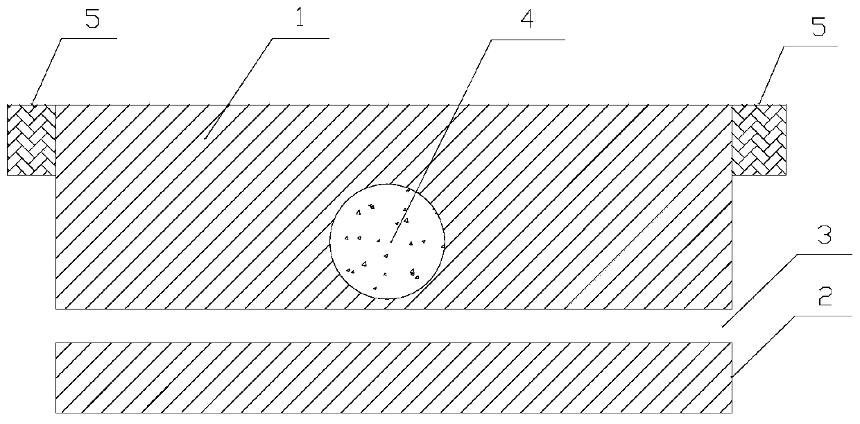
[0022] On the basis of Example 1, such as figure 2 As shown, the electrodes 5 are connected to both ends of the first metal plate 1 . The first metal plate 1 is used as the carrier of the current to be measured. The cavity 4 is circular, and the distance between the cavity 4 and the slit 3 is less than 100 nanometers, so that the surface plasmon polaritons in the slit 3 are coupled into the cavity 4 . The distance from the cavity 4 to the side of the first metal plate 1 away from the slit 3 is greater than 100 nanometers and less than 400 nanometers, that is to say, the distance between the cavity 4 figure 2 The distance between the tops of the first metal plate 1 is greater than 100 nanometers and less than 400 nanometers. It is designed so that the current to be measured not only flows from the area between the cavity 4 and the slit 3, but also flows from the area from the cavity 4 to the top of the first metal plate 1, and the direction of the current flowing from the t...

Embodiment 3

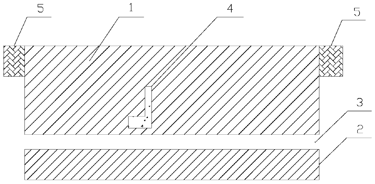
[0024] On the basis of Example 2, such as image 3 As shown, the cavity 4 is L-shaped. The cavity 4 can also be U-shaped, V-shaped and other shapes. When the cavity 4 has these shapes, the currents near the cavity 4 are different, the excited magnetic fields are different, and the changes to the refractive index of the magnetic fluid are different, resulting in serious non-uniform distribution of the refractive index in the cavity 4 . The resonance peak of the cavity is split and the resonance peak is narrower, which improves the detection sensitivity.


PUM


Abstract

The invention relates to a current detector based on a metal-dielectric-metal waveguide. The current detector comprises a substrate, and a first metal plate, a second metal plate and electrodes whichare arranged on the substrate. The first metal plate and the second metal plate are arranged in parallel, and a gap is formed between the first metal plate and the second metal plate, so as to form ametal-dielectric-metal waveguide. The electrodes are connected to the two ends of the metal plate on either side of the gap. A cavity is formed in the first metal plate, and a magnetic fluid is arranged in the cavity. When a current to be detected flows through the first metal plate or the second metal plate, a magnetic field is generated at the magnetic fluid to change the refractive index of themagnetic fluid and further change the resonance wavelength of the cavity, and the current intensity can be detected by detecting the change of the resonance wavelength. According to the current detector, either metal plate forming the metal-dielectric-metal waveguide is used for conducting a current and generating a magnetic field, so that the current detector has the advantages of small structural size, high detection sensitivity, wide amplitude of current intensity detection, and the like.

Description

technical field [0001] The invention relates to the field of current detection, in particular to a current detector based on a metal-dielectric-metal waveguide. Background technique [0002] Current intensity is a basic physical quantity. The detection of current intensity involves not only the measurement of strong currents for the safety of power systems, but also the measurement of weak currents in microsystems. The traditional current detection technology is mostly electromagnetic induction current transformer, which is bulky and heavy, and cannot realize weak current detection in microsystems. [0003] The current detection based on the optical principle has the advantages of strong anti-electromagnetic interference ability and relatively accurate measurement. Most current detectors based on optical principles are based on optical fiber structure, and the birefringence effect of optical fiber material reduces the detection performance of this type of detector. Conte...

Claims


Application Information

Patent Timeline
IPC IPC(8): G01R19/00G01R15/24
CPCG01R15/245G01R19/0092
Inventor 不公告发明人
Owner 西安柯莱特信息科技有限公司
Why Eureka
Try Eureka