Laser perforating detection method and laser cutting machine

A laser cutting machine, laser perforation technology, applied in photometry, laser welding equipment, optical radiation measurement and other directions, can solve the problem of cutting process decline and other problems, achieve the effect of convenient debugging, convenient assembly, and improve processing efficiency.

Active Publication Date: 2019-11-22
JINAN BODOR LASER CO LTD
View PDF5 Cites 1 Cited by
  • Summary
  • Abstract
  • Description
  • Claims
  • Application Information

AI Technical Summary

Problems solved by technology

[0005] The object of the present invention is to provide a laser perforation detection method and a laser cutting machine, which are used to solve the defect that the laser perforation in the prior art causes the cutting process to decline by setting a fixed time

Method used


Image

  • Laser perforating detection method and laser cutting machine
  • Laser perforating detection method and laser cutting machine
  • Laser perforating detection method and laser cutting machine

Examples


Embodiment 1

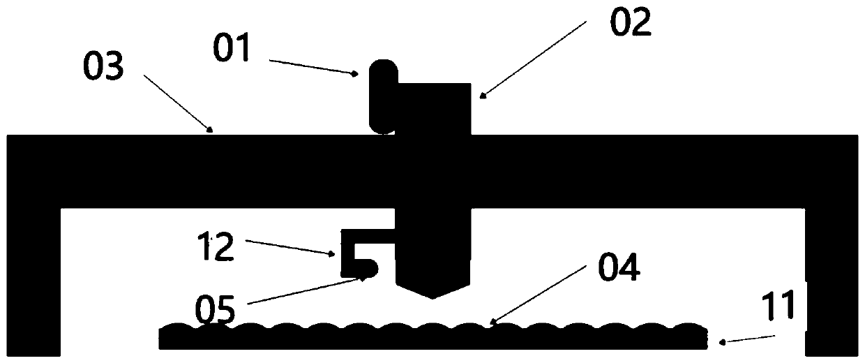
[0031] figure 1 A schematic diagram of the structure of a laser perforation detection device in an embodiment of the present invention is shown. The laser perforation detection device in this embodiment is applied to a laser cutting machine. Generally, a laser cutting machine includes: a laser head body, and controls the movement of the laser head body And the main control system that emits laser light. The laser perforation detection device of this embodiment includes: a signal processing unit 01 and a main sensor;

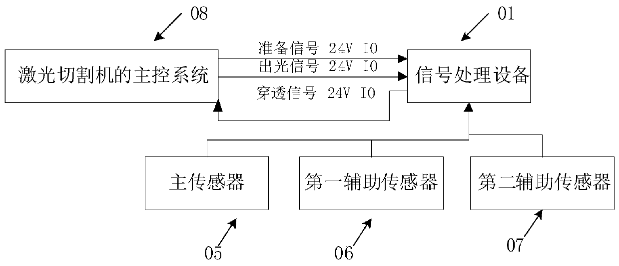
[0032] The signal processing unit 01 is installed on the laser head body 02, and the signal processing unit 01 is connected to the main control system 08 (such as image 3 shown);

[0033] The main sensor 05 used to detect the signal of the laser penetrating the plate, wherein the main sensor is fixed on the support 12, the support 12 is fixedly installed on the laser head body 02, and the detection direction of the main sensor is perpendicular to the The lase...

Embodiment 2

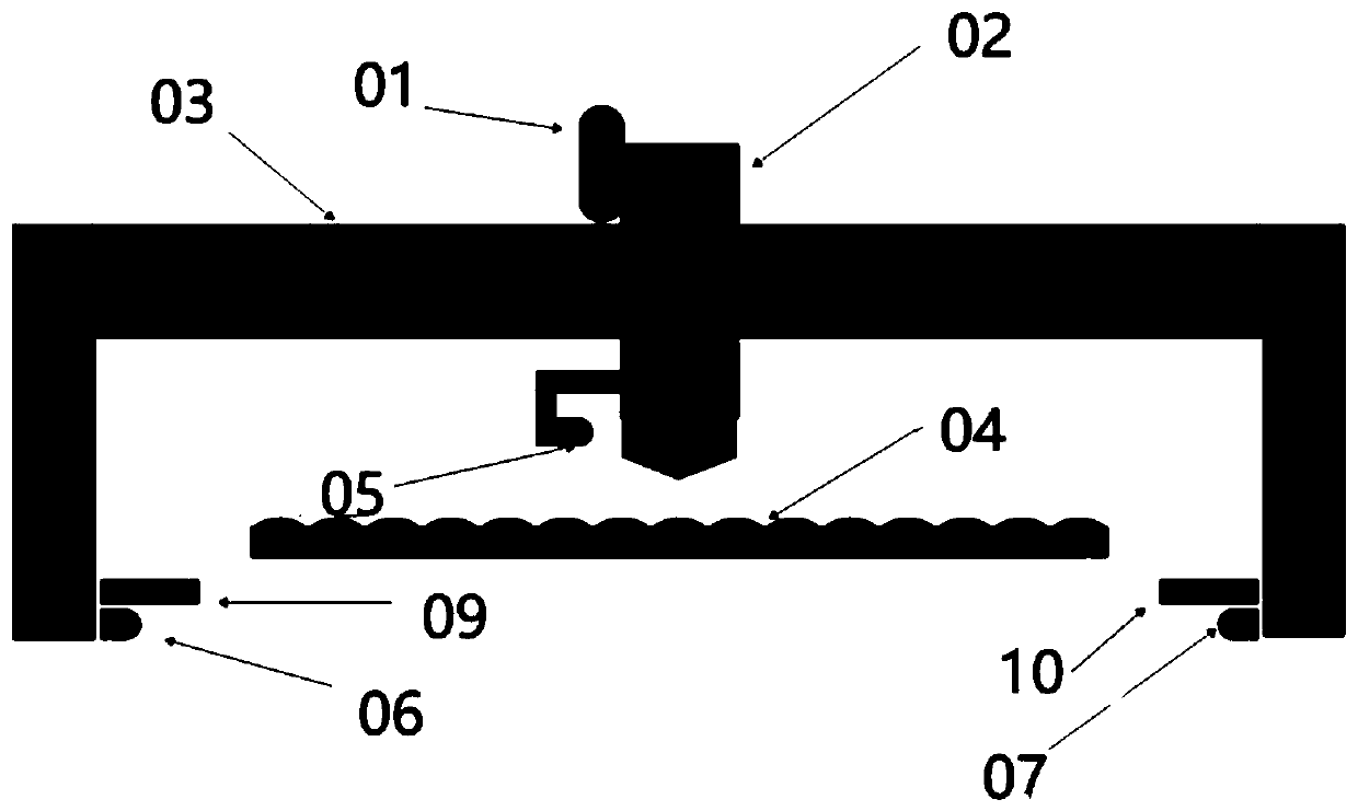
[0064] Based on the aforementioned figure 1 and figure 2 As shown in the laser perforation device, this embodiment provides a laser perforation detection method, such as Figure 4 As shown, the method of this embodiment is applied to a laser cutting machine, and its execution subject may be the main control system of the laser cutting machine. The laser perforation detection method of this embodiment may include:

[0065] 401. The main control system of the laser cutting machine sends the laser output signal to the signal processing unit;

[0066] 402. The main control system receives the penetration signal fed back by the signal processing unit; the penetration signal is the laser perforation obtained by processing the signal processing unit according to the detection signals of all sensors during the light emission period of the laser head body The state is a signal of penetration state;

[0067] 403. The main control system performs closed-loop control during the laser ...


PUM


Abstract

The invention discloses a laser perforating detection method and a laser cutting machine. A signal processing unit and at least one sensor for detecting signals indicating that laser penetrates through a plate are arranged on a laser head body of the laser cutting machine, and the sensors are located on the outer portion of the laser head body and electrically connected with the signal processingunit. The method comprises the steps that a main control system of the laser cutting machine sends a laser emitting signal to the signal processing unit; the main control system receives a penetrating-through signal fed back by the signal processing unit; in the laser-emitting period of the laser head body, the signal processing unit processes detecting signals of all the sensors, and a signal with a penetrating-through state as a obtained laser perforating state is the penetrating-through signal; and the main control system carries out closed-cycle control over the laser perforating detectingprocess according to the penetrating-through signal. By means of the method, the defect that the cutting technology descends as a fixed duration is set for laser perforating in the existing technology can be overcome.

Description

technical field [0001] The invention relates to laser cutting technology, in particular to a laser perforation detection method and a laser cutting machine. Background technique [0002] Laser cutting equipment often needs to perform laser perforation on the plate when cutting the plate, but the traditional laser cutting equipment cannot distinguish whether the laser penetrates the plate, and can only rely on the time parameters set by the main control system of the laser cutting machine to time End the laser perforation process, but this method will lead to two problems: 1. Due to the interference of various factors during the laser perforation process, it is difficult to maintain a constant value for the laser perforation time. If the time setting is too short, the laser cannot penetrate the plate effectively. 2. Since it is difficult to maintain a fixed value for laser perforation time, users are often conservative when setting this parameter, which will cause waste of p...

Claims


Application Information

Patent Timeline
Patent Type & Authority Applications(China)
IPC IPC(8): B23K26/382B23K26/08B23K26/70G01V8/20G01J1/04G01J1/42
CPCB23K26/382B23K26/702G01V8/20G01J1/0403G01J1/42B23K26/0869
Inventor 牛满钝林高令陈传明曹旭赵敬德刘凯闫彭彭马春飞
Owner JINAN BODOR LASER CO LTD
Why Eureka
Try Eureka