Al technical title is built by PatSnap Al team. It summarizes the technical point description of the patent document.
A technology for wellbore trajectory and control tools, applied in the automatic control system of drilling, drilling equipment, directional drilling, etc., can solve the problems of low ROP, difficult orientation in directional sections, etc., achieve low cost and improve wellbore cleaning ability , the effect of good economical applicability
Active Publication Date: 2019-11-22
BC P INC CHINA NAT PETROLEUM CORP +1
View PDF9 Cites 6 Cited by
Summary
Abstract
Description
Claims
Application Information
AI Technical Summary
This helps you quickly interpret patents by identifying the three key elements:
Problems solved by technology
Method used
Benefits of technology
Problems solved by technology
[0003] The purpose of the present invention is to provide a half-rotary wellbore trajectory control tool, which can realize the function of rotating the upper drill string to drill and the downhole power drilling tool to perform sliding and directional drilling at the same time through the torque "clutch-on" mode, thereby greatly reducing the During sliding directional drilling, the friction of the drill string can relieve the back pressure, stabilize the tool face, and improve the trajectory control ability of the wellbore, so as to solve the problems of difficult orientation and low ROP in the directional section of the long-horizontal horizontal well in Weiyuan
Method used
Image
Click on the blue label to locate the original text in one second.
Reading with bidirectional positioning of images and text.
Examples
Embodiment
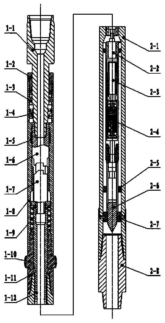
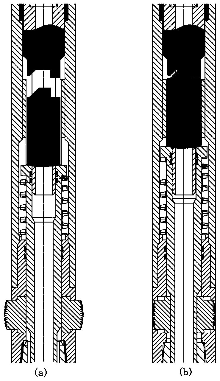
[0031] An 8 1 / 2″ wellbore uses a downhole motorized drilling tool assembly for conventional sliding directional drilling in the horizontal section, and the half-rotary well trajectory control tool is installed in the drill string at a certain distance from the rear end of the downhole motor. The surface Send out a set of bypass valve shunt and pressure relief signals at a certain time interval, and transmit them to the half-rotary wellbore trajectory control tool. The pressure sensor built in the downhole electronic control unit of the tool will drive the DC motor after receiving the pressure change signal 2-3 Make an action to drive the center rod 1-12 to move up. The upper half clutch 1-6 and the lower half clutch 1-7 leave to realize the pipe string turning up and down. At this time, the turntable can rotate normally at a certain speed, and the driller has a small drilling pressure. Send the drill and observe whether the tool face is stable. If the tool face is relatively st...
PUM
Abstract
The invention belongs to the technical filed of drilling in the field of oil and natural gas, in particular to a half-way rotary well track control tool. The half-way rotary well track control tool ischaracterized in that the half-way rotary well track control tool comprises a shell, a support sleeve, an outer barrel, a mechanical clutch pup joint arranged in the shell, and an electric control pup joint arranged in the outer barrel, the electric control pup joint comprises an electronic module, a direct current motor and a telescopic mechanism, the mechanical clutch pup joint comprises an upper joint, an upper half clutch, a center rod, a lower half clutch, an upper pressing cap, a bearing assembly, a seal combination, a group of piston claw, a reset spring, the bottom of the center rod is connected with the telescopic mechanism in a threaded mode, the lower half clutch is connected with the upper part of the center rod, and the bottom end of the outer barrel is provided with a lowerjoint. According to the half-way rotary well track control tool, use is convenient, the cost is low, reliable and effective well track control can be realized, an upper part pipe column of the half-way rotary well track control tool completely rotates, ranges of friction reduction and drag reduction are large, and at the same time, the well cleaning ability can be improved; and compared with rapidsliding drilling, technical advantages are obvious, and compared with a rotary guide drilling tool, economic applicability is good.
Description
technical field [0001] The invention belongs to the technical field of drilling in the field of petroleum and natural gas, and in particular relates to a half-rotary wellbore trajectory control tool. Background technique [0002] With the development of oilfields in the middle and later stages and the development of unconventional oil and gas resources such as shale gas, the application of long horizontal section horizontal wells, cluster wells, extended reach wells and five-section wells is becoming more and more extensive. The problem caused by high frictional resistance is particularly prominent, which seriously restricts the extension of the length of the horizontal section and the speed increase of directional drilling. In conventional directional drilling, due to the high wear resistance, the back pressure cannot be effectively transmitted to the drill bit, and problems such as tool face instability and slow ROP often occur. Rotary steerable drilling can solve the fri...
Claims
Application Information
Patent Timeline
Application Date:The date an application was filed.
Publication Date:The date a patent or application was officially published.
First Publication Date:The earliest publication date of a patent with the same application number.
Issue Date:Publication date of the patent grant document.
PCT Entry Date:The Entry date of PCT National Phase.
Estimated Expiry Date:The statutory expiry date of a patent right according to the Patent Law, and it is the longest term of protection that the patent right can achieve without the termination of the patent right due to other reasons(Term extension factor has been taken into account ).
Invalid Date:Actual expiry date is based on effective date or publication date of legal transaction data of invalid patent.