Stator excitation flywheel pulse reluctance generator system

A reluctance motor and generator technology, applied in synchronous generators, electrical components, electromechanical devices, etc., can solve the problems of low power density, low energy density, large volume and weight, etc., and achieve high power density and energy density. Small and simple system structure

Inactive Publication Date: 2019-11-22
HARBIN INST OF TECH
View PDF6 Cites 0 Cited by
  • Summary
  • Abstract
  • Description
  • Claims
  • Application Information

AI Technical Summary

Problems solved by technology

[0006] The purpose of the present invention is to solve the problems of low power density, low energy density and large volume and weight of existing pulse generator sets, and propose a stator excitation flywheel pulse reluctance generator system

Method used


Image

  • Stator excitation flywheel pulse reluctance generator system
  • Stator excitation flywheel pulse reluctance generator system
  • Stator excitation flywheel pulse reluctance generator system

Examples


specific Embodiment approach 1

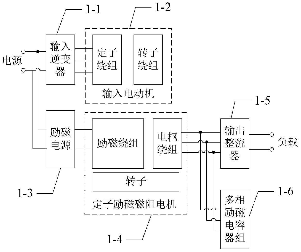
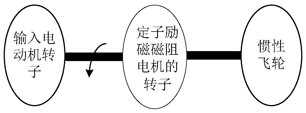
[0025] Specific implementation mode one: combine figure 2 and image 3 Describe this embodiment, a stator excitation flywheel pulse reluctance generator system described in this embodiment includes an input inverter 1-1, an input motor 1-2, an excitation power supply 1-3, a stator excitation reluctance motor 1- 4. Output rectifier 1-5, multi-phase excitation capacitor bank 1-6 and inertial flywheel;

[0026] The output end of the input inverter 1-1 is connected to the lead wire of the stator winding of the input motor 1-2; the output end of the excitation power supply 1-3 is connected to the lead wire of the excitation winding of the stator excitation reluctance motor 1-4, The lead wires of the multiphase armature windings of the stator excitation reluctance motor 1-4 are connected to the AC input terminals of the output rectifier 1-5, and the output terminals of the multiphase armature windings of the stator excitation reluctance motor 1-4 are connected in parallel with the...

specific Embodiment approach 2

[0028] Specific implementation mode two: combination image 3 and Figure 4 Describe this embodiment, a stator excitation flywheel pulse reluctance generator system described in this embodiment includes an input inverter 2-1, an input motor 2-2, an excitation power supply 2-3, a stator excitation reluctance motor 2- 4. Output rectifier 2-5, multi-phase excitation capacitor bank 2-6 and inertial flywheel;

[0029] The output end of the input inverter 2-1 is connected with the lead-out wire of the stator winding of the input motor 2-2; the output end of the excitation power supply 2-3 is connected with the lead-out wire of the excitation winding of the stator excitation reluctance motor 2-4, The two output terminals of each phase of the armature winding of the excitation reluctance motor 2-4 are respectively connected with the two AC input terminals of a single-phase rectifier 2-5, and at the same time, each phase of the stator excitation reluctance motor 2-4 The two output en...

specific Embodiment approach 3

[0031] Specific implementation mode three: combination Figure 5 and Figure 6 Describe this embodiment, a stator excitation flywheel pulse reluctance generator system described in this embodiment includes an input inverter 3-1, an input permanent magnet AC motor 3-2, a stator excitation reluctance motor 3-3, an output Rectifier 3-4, multi-phase excitation capacitor bank 3-5 and inertial flywheel;

[0032] The output terminal of the input inverter 3-1 is connected to the lead-out line of the stator winding of the input permanent magnet AC motor 3-2; the positive and negative pole output terminals of the DC bus of the input inverter 3-1 are connected to the stator excitation reluctance motor 3-3 The lead wires of the excitation winding of the stator excitation reluctance motor 3-3 are connected together, the lead wires of the multiphase armature winding of the stator excitation reluctance motor 3-3 are connected with the AC input end of the output rectifier 3-4, and the multip...


PUM


Abstract

The invention discloses a stator excitation flywheel pulse reluctance generator system, belongs to the field of motors, and aims to solve the problems of low power density, low energy density and large size and weight of an existing pulse generator set. The output end of an input inverter is connected with an outgoing line of a stator winding of an input motor; the output end of an excitation power supply is connected with an excitation winding leading-out wire of a stator excitation reluctance motor, a multi-phase armature winding leading-out wire of the stator excitation reluctance motor isconnected with the alternating-current input end of an output rectifier, and the output end of a multi-phase armature winding of the stator excitation reluctance motor is connected with a multi-phaseexcitation capacitor bank in parallel. A rotor of the input motor and a rotor of the stator excitation reluctance motor are coaxially connected with an inertia flywheel. The stator excitation flywheel pulse reluctance generator system has the advantages of simple structure, low cost, high reliability, adjustable output voltage and the like, can be used as a high-capacity pulse power supply, and has a good application prospect in the fields of nuclear fusion test technology, plasma and electromagnetic emission technology and the like.

Description

technical field [0001] The invention belongs to the field of motors. Background technique [0002] The flywheel pulse generator is a flywheel energy storage device that uses the large inertia of the shaft system to store energy, coaxial motor and generator to realize electromechanical energy conversion; there are two types of flywheel energy storage devices that are currently in use or are being developed: the first The second is that the power levels of energy storage and energy release are equivalent, and one motor can be used to alternately realize the functions of electric power generation and power generation. The small and medium-capacity magnetic levitation flywheel energy storage system is of this type, which has the characteristics of compact structure and high efficiency, and is generally used as a flywheel battery; The second is that the energy storage power is more than an order of magnitude smaller than the energy release power, and the two motors realize the el...

Claims


Application Information

Patent Timeline
Patent Type & Authority Applications(China)
IPC IPC(8): H02K7/02H02K19/26
CPCH02K7/025H02K19/26Y02E60/16Y02E70/30
Inventor 寇宝泉赵元胜张浩泉
Owner HARBIN INST OF TECH
Why Eureka
Try Eureka