
Mold core sand removal method for low-pressure cast turbocharger shell

A turbocharger and low-pressure casting technology, which is applied in the field of aluminum alloy low-pressure casting technology, can solve the problems of inner wall scratches, complex shell structure, and slow efficiency of castings, and achieve the effect of ensuring quality and improving sand cleaning efficiency

Inactive Publication Date: 2019-11-26
江苏新安驰铝业有限公司
View PDF10 Cites 0 Cited by
  • Summary
  • Abstract
  • Description
  • Claims
  • Application Information

AI Technical Summary

Problems solved by technology

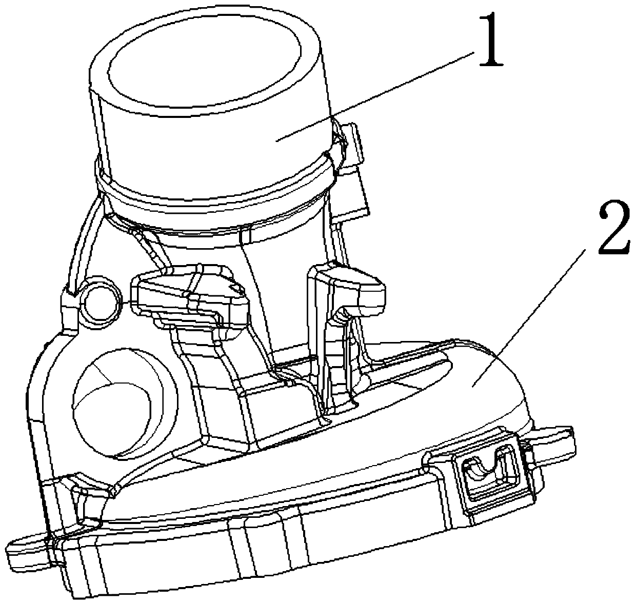
[0013] After obtaining the casing casting of the turbocharger, it is necessary to clean the inner core sand, also known as coated sand, before the next step of machining, but the structure of the turbocharger casing is complex, such as figure 1 As shown, its structure is that there is an end above the air inlet, and there is a flat shell under the end. The diameter of the end is about 1 / 2 of the flat shell, and the end part will be reserved during casting. A part of the entity is convenient to wrap the entire core and then cut it later. The core in the flat shell needs to be discharged through the end part, which is troublesome. At present, the commonly used processing method is to use a small grinding wheel with a grinding wheel head at the front end for grinding. Insert the stirring shaft into the end for sand cleaning operation, which has the following defects:
[0014] 1. The efficiency is slow, the diameter of the grinding head is small, and the castings need to be cleaned one by one, and some places have four corners, and the grinding head cannot reach the dead corner;
[0015] 2. The grinding head will inevitably touch the inner wall of the casting when cleaning the sand, causing certain scratches on the inner wall of the casting, affecting the quality and service life of the casting

Method used


Image

  • Mold core sand removal method for low-pressure cast turbocharger shell

Examples


Embodiment Construction

[0031] The shell of the turbocharger is an important part of the turbocharger. The principle of exhaust gas turbocharging is to use the exhaust gas from the engine to drive the turbine impeller to drive the compressor impeller to compress the air to increase the intake pressure and increase the air charge.

[0032] When the engine speed increases, the exhaust gas discharge speed and the turbine speed also increase synchronously. At this time, the exhaust gas does more work on the turbine, and the compressor impeller compresses more air into the engine combustion chamber, so that the engine fuel can be fully burned and increased. Improve engine efficiency, generate greater power, reduce exhaust emissions, and increase the intake pressure of the engine, mainly by the exhaust gas turbocharger installed on the engine.

[0033] After obtaining the casing casting of the turbocharger, it is necessary to clean the inner core sand, also known as coated sand, before the next step of mach...


PUM


Abstract

A mold core sand removal method for a low-pressure cast turbocharger shell comprises the steps that the redundant part of the end of an aluminum alloy turbocharger shell casting with a sand core is cut off by cutting machining equipment; the end of the turbocharger shell casting with molding sand is downward, and the molding sand loosened when the end is cut just now is poured out; the turbocharger shell casting with the molding sand is arranged to be subjected to T6 heat treatment, and most molding sand of the turbocharger shell casting obtained through T6 heat treatment and with the loosenedmolding sand is removed manually with a sand drawing tool; and the turbocharger shell casting which is not cleaned up is transferred to a mold sandblasting machine workshop, a sandblasting head of amold sandblasting machine is aligned with the residual molding sand part of an inner cavity of the turbocharger shell casting, and sandblasting treatment is conducted. The sand is removed in the modecombining T6 heat treatment and the mold sandblasting machine, sand removal efficiency can be fast improved, the inner wall of the casting is not damaged while sand removal quality is ensured, and sand removal efficiency is improved greatly.

Description

technical field [0001] The invention relates to the technical field of aluminum alloy low-pressure casting technology, in particular to a core sand cleaning method for a low-pressure casting turbocharger casing. Background technique [0002] The shell of the turbocharger is an important part of the turbocharger. The principle of exhaust gas turbocharging is to use the exhaust gas from the engine to drive the turbine impeller to drive the compressor impeller to compress the air to increase the intake pressure and increase the air charge. [0003] When the engine speed increases, the exhaust gas discharge speed and the turbine speed also increase synchronously. At this time, the exhaust gas does more work on the turbine, and the compressor impeller compresses more air into the engine combustion chamber, so that the engine fuel can be fully burned and increased. Improve engine efficiency, generate greater power, reduce exhaust emissions, and increase the intake pressure of the ...

Claims


Application Information

Patent Timeline
Patent Type & Authority Applications(China)
IPC IPC(8): B22D18/04B22D29/00
CPCB22D18/04B22D29/003
Inventor 陈奎涌何伟祥吴良引陶宇张永康李巍
Owner 江苏新安驰铝业有限公司
Learn More