Automatic slitting machine for arc-shaped paperboard

A technology of arc and cardboard, which is applied in the field of automatic cutting machine for arc cardboard, can solve problems such as collision and deformation of arc cardboard, and achieve the effect of tight connection of actions and high degree of automation

Active Publication Date: 2019-11-26
阜阳市鑫格特机电设备有限公司
View PDF7 Cites 1 Cited by
  • Summary
  • Abstract
  • Description
  • Claims
  • Application Information

AI Technical Summary

Problems solved by technology

[0005] In view of the above problems, the present invention provides an arc-shaped cardboard automatic cutting machine, which cuts the paper tube by using a cutting mechanism, and inserts the arc-shaped plate formed by cutting along the guide channel into the tube formed by the expansion of the dust-absorbing air bag. In the ring-shaped buffer tank, the arc-shaped cardboard is protected by the buffer formed by the expansion of the dust-absorbing air bag, and then the arc-shaped cardboard is slowly turned over and placed on the receiving tray during the contraction of the dust-absorbing air bag, which solves the problem The technical problem of collision and deformation of curved cardboard after cutting

Method used


Image

  • Automatic slitting machine for arc-shaped paperboard
  • Automatic slitting machine for arc-shaped paperboard
  • Automatic slitting machine for arc-shaped paperboard

Examples


Embodiment 1

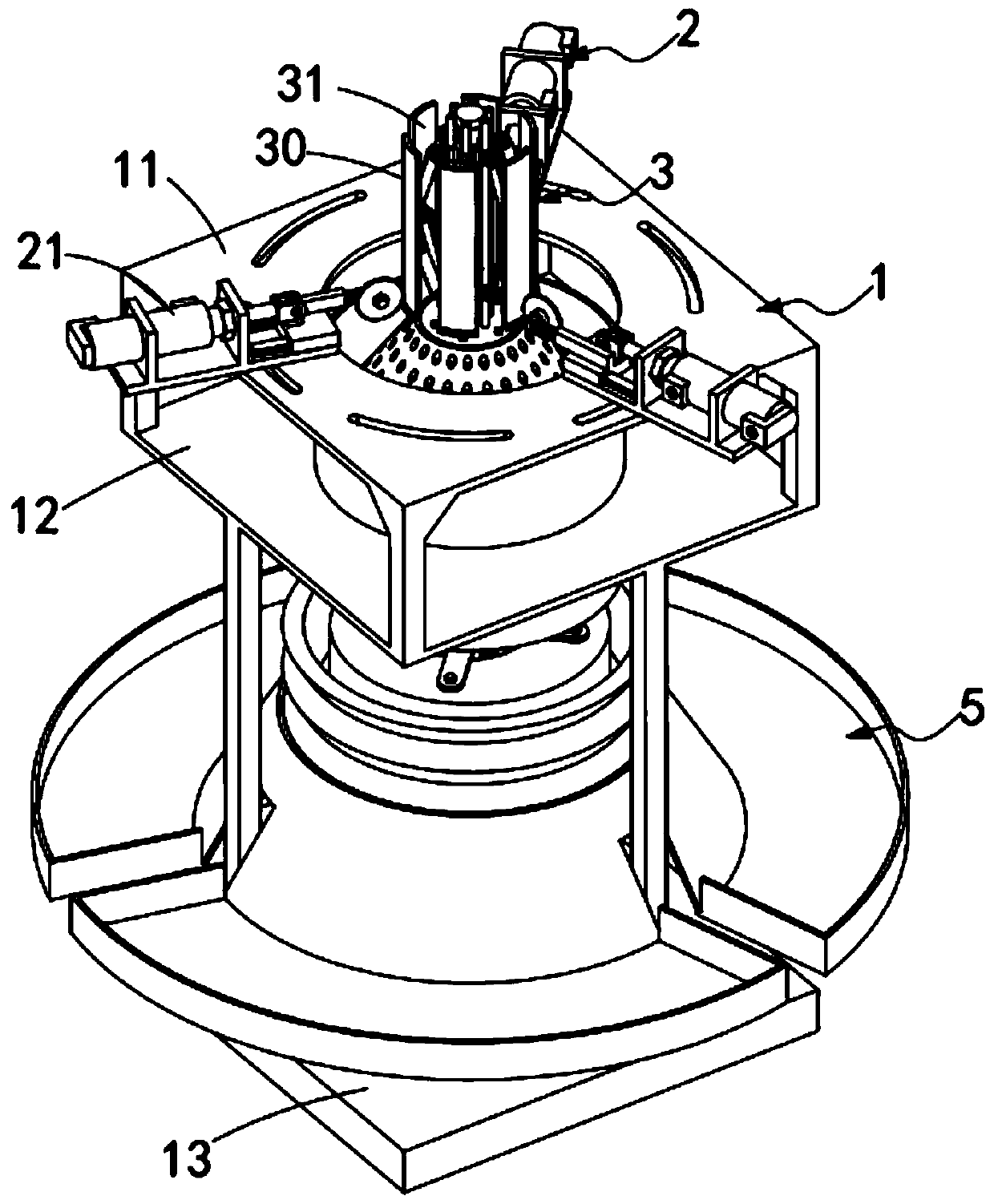
[0069] Such as Figure 1 to Figure 3 As shown, a high-quality curved cardboard automatic slitting machine, including:

[0070] Frame 1, the frame 1 is a frame-shaped setting, which includes a first mounting plate 11 at the top, a second mounting plate 12 at the middle and a third mounting plate 13 at the bottom;

[0071] Cutting mechanism 2, described cutting mechanism 2 is installed on the described first mounting plate 11, and it comprises several cutting assemblies 21 that are equidistantly arranged along the axis circle of described first mounting plate 11, and this cutting assembly 21 All point to the center of the first mounting plate 11;

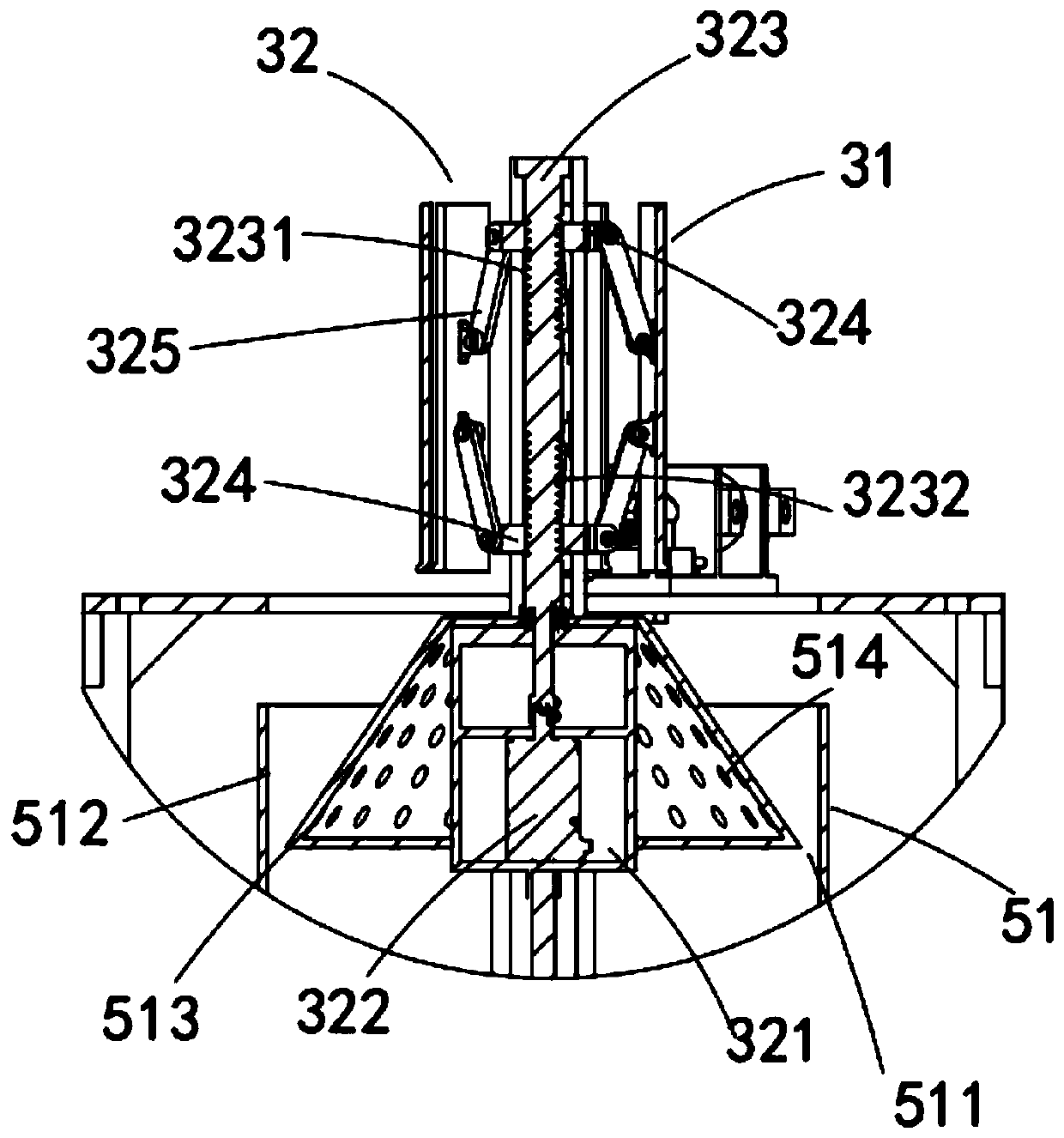
[0072] The material receiving mechanism 3, the material receiving mechanism 3 is installed on the axis of the frame 1, it rises and falls along the axis of the frame 1 and penetrates the first mounting plate 11 and the second mounting plate 12 to set , and the material receiving mechanism 3 includes a number of material receiving pl...

Embodiment approach

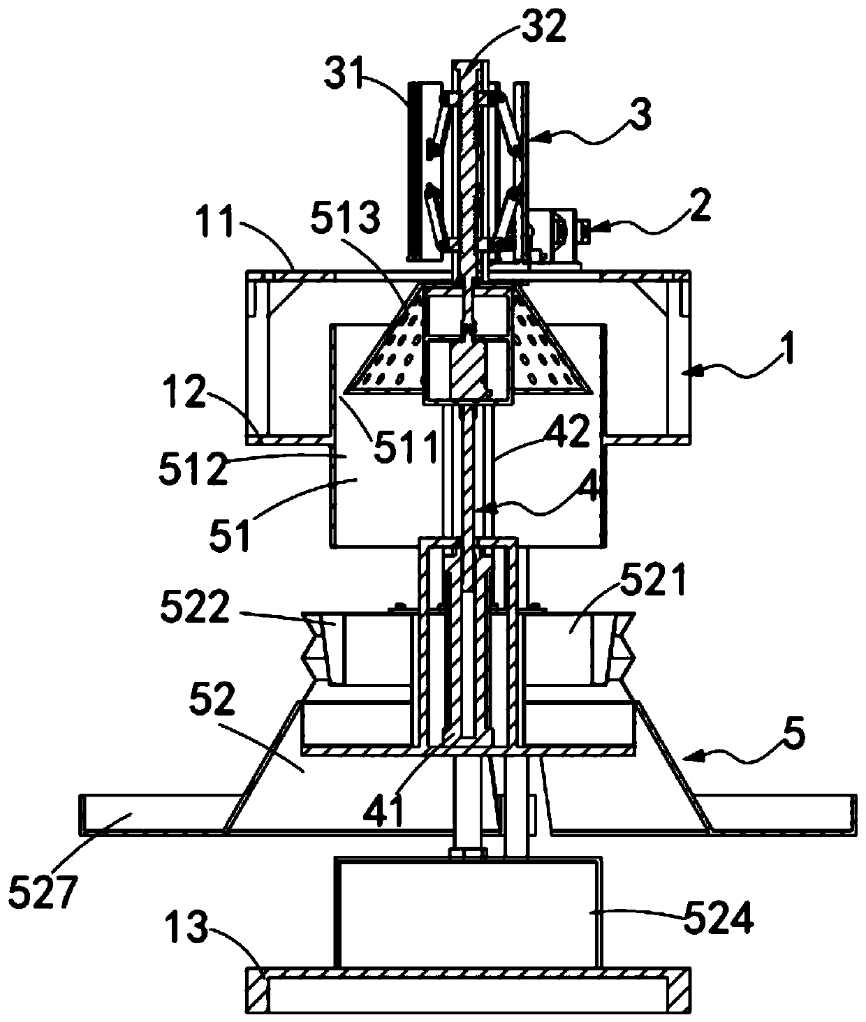
[0101] Such as figure 2 and Figure 10 As shown, as a preferred embodiment, the lifting mechanism 4 includes:

[0102] Lifting the cylinder 41, the lifting cylinder 41 is vertically arranged between the second mounting plate 12 and the third mounting plate 13, and its cylinder shaft 411 pushes the material receiving mechanism 3 vertically upward; and

[0103] The guide rod 42 is equidistantly arranged around the axis of the lifting cylinder 41 , its upper end is fixedly connected with the material receiving mechanism 3 , and its lower end slides through the frame 1 .

[0104] Further, the guide assembly 51 includes:

[0105] A guide tube 512, the guide tube 512 is vertically installed at the center of the second mounting plate 12, and the material receiving mechanism 3 is arranged up and down in the inner circumferential side wall of the guide tube 512; and

[0106] The guide platform 513, the guide platform 513 is fixedly connected with the material receiving mechanism 3,...


PUM


Abstract

The invention provides an automatic slitting machine for an arc-shaped paperboard. The automatic slitting machine comprises a slitting mechanism, a material bearing mechanism sleeved with a paper tube, a lifting mechanism for lifting the paper tube, and a buffering and dust collecting mechanism for performing dust collection treatment on paper scraps generated in the paper tube cutting process andbuffering the arc-shaped paperboard obtained after cutting. The slitting mechanism is used for slitting the paper tube, the arc-shaped paperboard formed after slitting is inserted into a circular buffer groove formed through expansion of a vacuum bag along a guide channel. The arc-shaped paperboard is protected through buffering formed by the expansion of the vacuum bag. In the vacuum bag contraction process, the arc-shaped paperboard is slowly turned over to a receiving plate for placement, and the technical problem of collision deformation of the arc-shaped paperboard after cutting is solved.

Description

technical field [0001] The invention relates to the technical field of cutting and processing machinery for curved cardboard, in particular to an automatic cutting machine for curved cardboard. Background technique [0002] In toy processing, especially the processing of pet toys, a large amount of paper tubes and curved cardboards formed after cutting paper tubes are required, and in the process of cutting paper tubes to form curved cardboards, a large amount of The paper dust pollutes the working environment, and the arc-shaped cardboard formed by cutting falls directly on the ground or on the cutting platform, which directly causes the corners of the arc-shaped cardboard to collide and deform. [0003] Patent No. CN201720546952.2 discloses a dust removal device for paper tube cutting, including a cutting chamber, a dust suction fan and a dust removal chamber; The cutting chamber is divided into a cutting chamber and a vacuum chamber; the cutting chamber is provided with ...

Claims


Application Information

Patent Timeline
Patent Type & Authority Applications(China)
IPC IPC(8): B26D1/18B26D3/10B26D7/01B26D7/18
CPCB26D1/18B26D3/10B26D7/01B26D7/1863B26D2007/013
Inventor 许磊
Owner 阜阳市鑫格特机电设备有限公司
Why Eureka
Try Eureka