
Amphibious lng tank container reloading ship and reloading method

A technology for tank containers and hulls, applied in shipbuilding, ship fittings, ship parts, etc., can solve problems such as complex structure and unfavorable production, and achieve the effects of fast operation speed, high safety and efficiency, and low cost

Active Publication Date: 2021-09-24
YICHANG DONGJIANG SHIPBUILDING CO LTD
View PDF7 Cites 0 Cited by
  • Summary
  • Abstract
  • Description
  • Claims
  • Application Information

AI Technical Summary

Problems solved by technology

However, the structure is more complicated, which is not conducive to production

Method used


Image

  • Amphibious lng tank container reloading ship and reloading method
  • Amphibious lng tank container reloading ship and reloading method
  • Amphibious lng tank container reloading ship and reloading method

Examples


Embodiment 1

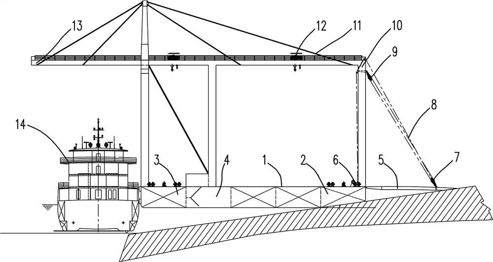
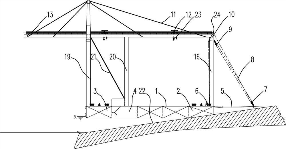
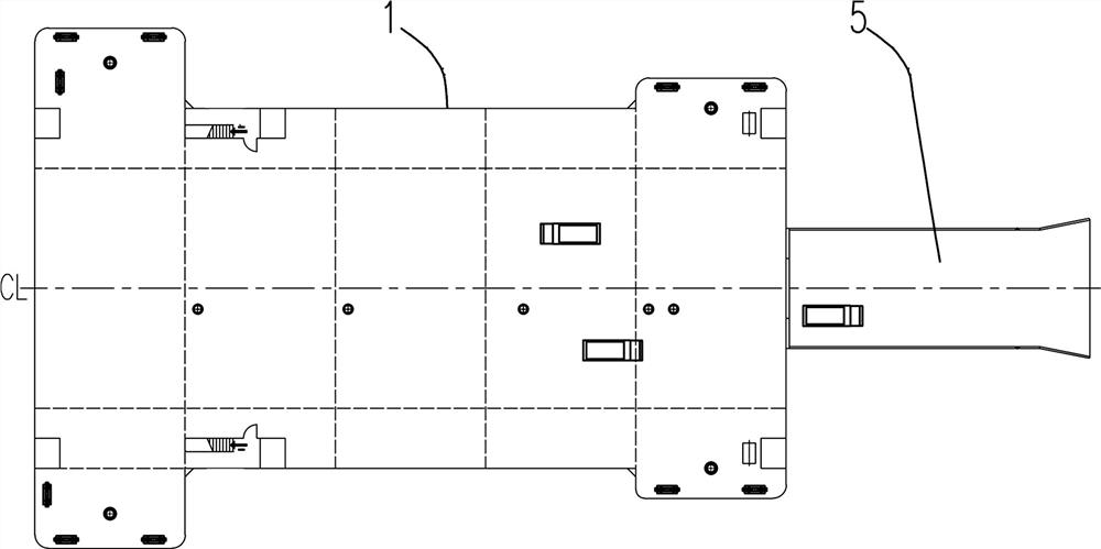
[0034] Such as Figure 2~5 Among them, an amphibious LNG reloading ship includes a hull 1, a hoisting device is arranged on the hull 1, a first ballast tank 2 is arranged at one end of the hull 1, and there are two first ballast tanks 2, and two ballast tanks at the bow of the hull One is arranged on each side, and the bottom of the first ballast tank 2 is provided with an inclined surface in contact with the ramp lane 22. Preferably, the inclination of the ramp lane 22 is 8°, and the inclined surface at the bottom of the first ballast tank 2 is also 8° accordingly. A wear-resistant material, such as rubber, is provided at the position of the slope. There is also a pump room 4 for adjusting the load in the first ballast tank 2;

[0035] An end of the hull 1 close to the first ballast tank 2 is provided with a driving ramp 5, preferably, the driving ramp 5 adopts a retractable structure. With this structure, by adjusting the load water in the first ballast tank 2, the hull 1 ...

Embodiment 2

[0045] On the basis of Example 1, such as figure 1 Among them, a method for reloading using the above-mentioned amphibious LNG reloading ship, comprising the following steps:

[0046] S1. Pull the hull 1 to the appropriate position of the ramp lane 22, and increase the load by injecting water into the first ballast tank 2 through the pump room 4, so that the bottom of the first ballast tank 2 is in contact with the ramp lane 22; The position close to the land base is towed by a cable, one end of the cable is connected to the electric winch installed at the tail of the hull 1, and the other end is connected to the ground cow on the slope lane 22, and the position of the hull 1 is realized by tightening or loosening the cable through the electric winch traction adjustment.

[0047] S2, fastening the stern and the figure-of-eight cable of the shore base, one end of the figure-of-sight cable is connected with the electric cable winch installed in the afterbody of the hull 1, and ...


PUM


Abstract

The invention provides an amphibious LNG reloading ship, which includes a hull, a lifting device is arranged on the hull, a first ballast tank is arranged at one end of the hull, the bottom of the first ballast tank is provided with an inclined surface in contact with the ramp lane, and There is a pump room for adjusting the load in the first ballast tank; there is a driving springboard at the end of the hull close to the first ballast tank. When in use, the hull is towed to an appropriate position on the ramp lane, and the load is increased by injecting water into the first ballast tank through the pump room, so that the bottom of the first ballast tank is in contact with the ramp lane; the figure-eight cables between the stern and the shore foundation are fastened, and the vehicle puts the LNG tank The LNG tank container is transported from the shore to the hull, and the LNG tank container is hoisted from the vehicle to the deck of the hull by the lifting device to realize the replacement of the LNG tank container. The invention overcomes the fluctuation of the water level and realizes the replacement of the tank container from the land to the LNG ship on the water by only occupying relatively small shoreline resources, and the operation speed is fast and the safety efficiency is high.

Description

technical field [0001] The invention relates to the field of marine LNG energy reloading, in particular to an amphibious LNG tank container reloading ship and a reloading method. Background technique [0002] LNG is the abbreviation of Liquefied Natural Gas (LNG). The main component is methane. It is recognized as the cleanest fossil energy on earth. Colorless, odorless, non-toxic and non-corrosive. There are many ships in my country's inland rivers, and the potential for water transportation is huge. The fuel storage method adopted by the LNG fuel-powered ship in the prior art is a fixed storage tank, because the fixed storage tank depends on the shore filling station or the shore filling pontoon to fill it, for example, it is recorded in the Chinese patent document CN106428445A It is a kind of mobile tanker, which adopts the way of filling for fuel supply. The construction of bunkering stations faces difficulties in site selection, huge investment, and long approval per...

Claims


Application Information

Patent Timeline
Patent Type & Authority Patents(China)
IPC IPC(8): B63B27/12B63B27/14B63B27/30B63J4/00
CPCB63B27/12B63B27/143B63B27/30B63J4/002
Inventor 姚智衡郭强波姚奉
Owner YICHANG DONGJIANG SHIPBUILDING CO LTD
Learn More