Phase change heat storage type heat supply system and control method thereof

A heat supply system and phase change heat storage technology, which is applied in heat storage heaters, fluid heaters, lighting and heating equipment, etc., can solve the problems of inability to ensure the efficiency of charging and discharging heat at the same time, and achieve the purpose of improving the efficiency of charging and discharging heat, and improving the efficiency of heat exchange. Thermal efficiency, the effect of improving system energy efficiency

Pending Publication Date: 2019-11-26
GREE ELECTRIC APPLIANCES INC
View PDF8 Cites 3 Cited by
  • Summary
  • Abstract
  • Description
  • Claims
  • Application Information

AI Technical Summary

Problems solved by technology

[0007] Therefore, the technical problem to be solved by the present invention is to overcome the defects that the phase change heat storage and heat supply system in the prior art cannot guarantee the efficiency of charging and discharging heat at the same time, as well as heat storage and user heat supply at the same time, so as to provide a phase change heat storage Type heating system and its control method

Method used


Image

  • Phase change heat storage type heat supply system and control method thereof
  • Phase change heat storage type heat supply system and control method thereof
  • Phase change heat storage type heat supply system and control method thereof

Examples


Embodiment 1

[0065] Embodiment 1 Preferably,

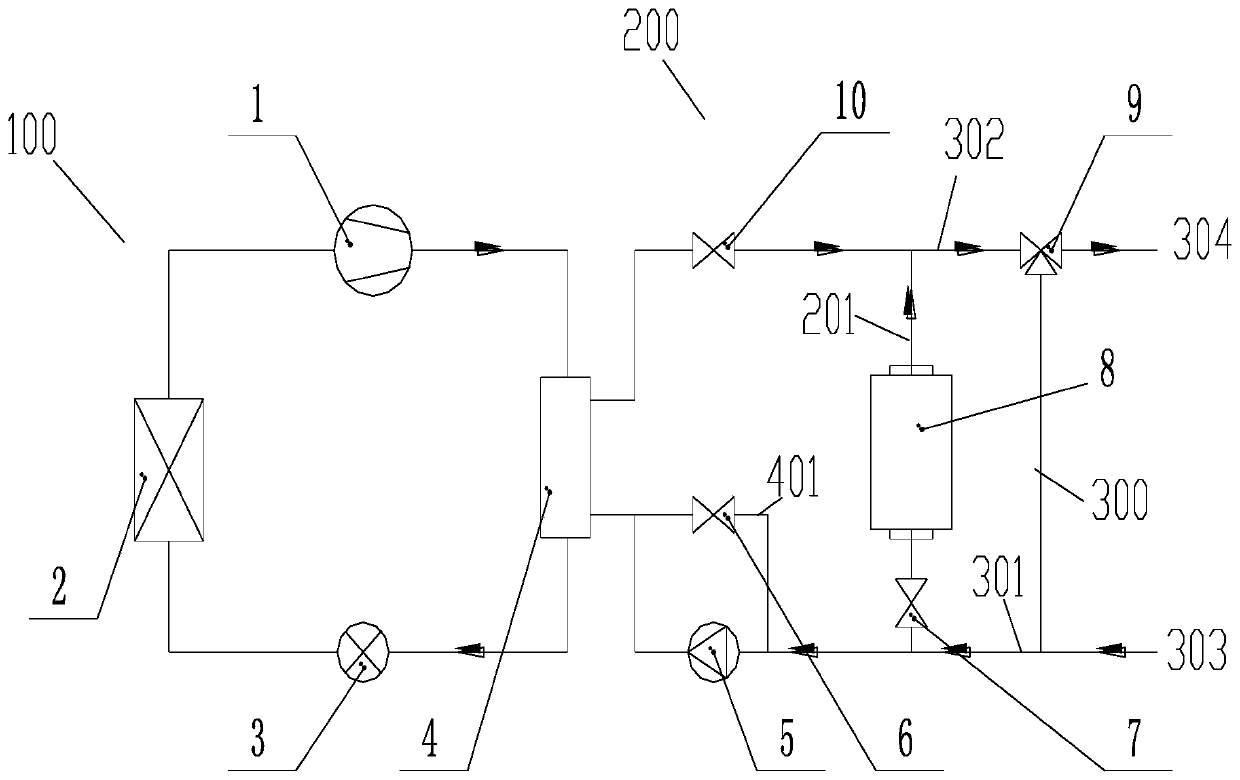
[0066] Such as figure 1 As shown, a first branch 401 is provided in parallel on the circulating water pump 5 , and a first cut-off valve 6 is provided on the first branch. This is the preferred structural form of Embodiment 1 of the present invention, which can effectively realize the parallel connection of the second heat exchanger 4 of the heat pump and the heat accumulator, and realize the second thermal energy in the joint heating mode of the heat pump heating and heat accumulator. The parallel connection of the exchanger and the heat accumulator simultaneously provides the user with water for heating. figure 1 Embodiment 1 of the phase change thermal storage water heater provided by the present invention. The system includes a heat pump heating loop and a water system heat storage and discharge loop. The heat pump heating circuit is composed of compressor 1, first heat exchanger 2, throttling device 3, second heat exchanger 4 and auxil...

Embodiment 2

[0069] Embodiment 2 Preferably,

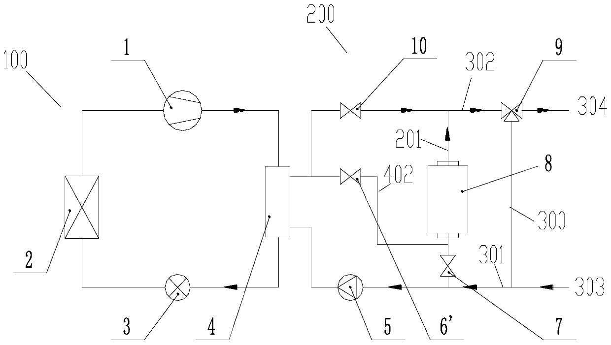
[0070] Such as figure 2 As shown, it also includes a second branch 402, one end of the second branch 402 is connected between the heat accumulator 8 and the second shut-off valve 7, and the other end is connected to the second heat exchanger 4 and the third cut-off valve 10, and a first cut-off valve '6' is also provided on the second branch 402. This is the preferred structural form of Embodiment 2 of the present invention, which can effectively realize the series connection of the second heat exchanger 4 of the heat pump and the heat accumulator, and realize the second thermal The exchanger and the heat accumulator are connected in series, and the second heat exchanger is located at the low-temperature end, and the heat accumulator is located at the high-temperature end, and at the same time, water is supplied to the user for heating.

[0071] figure 2 They are Embodiment 2 of the phase change thermal storage water heater provided by th...

Embodiment 3

[0074] Embodiment 3 Preferably,

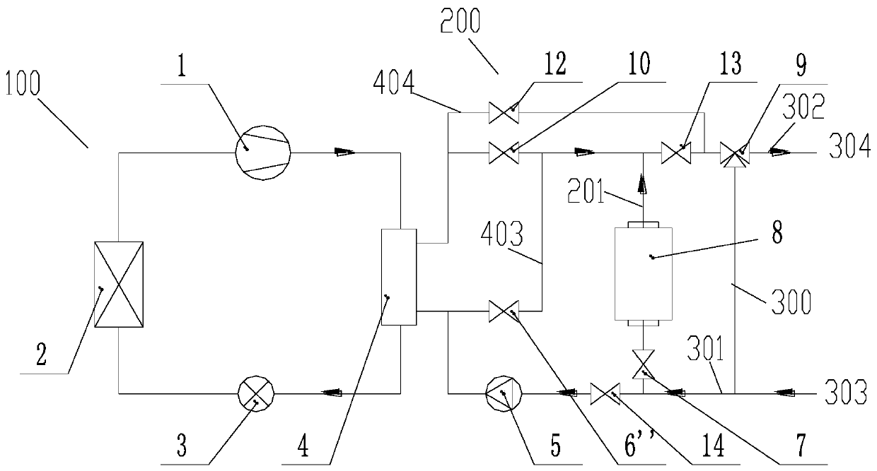
[0075] Such as image 3 As shown, it also includes a third branch 403, one end of the third branch 403 is connected to the position between the second end of the partial pipeline 201 and the third stop valve 10, and the other end is connected to the The position between the third end of the second heat exchanger 4 and the first end of the partial pipeline 201, and the third branch 403 is also provided with a first stop valve "6". This is the preferred structural form of Embodiment 3 of the present invention, which can effectively realize the series connection of the second heat exchanger 4 of the heat pump and the heat accumulator. The series connection of the exchanger and the heat accumulator, and the second heat exchanger is located at the high-temperature end, and the heat accumulator is located at the low-temperature end, and at the same time, water is supplied to the user for heat supply. At this time, the heating energy efficiency is h...


PUM


Abstract

The invention provides a phase change heat storage type heat supply system and a control method thereof. The phase change heat storage type heat supply system comprises a refrigerant circulation loopand a water circulation loop, wherein the refrigerant circulation loop is provided with a compressor, a first heat exchanger, a throttling device and a second heat exchanger; the water circulation loop is provided with a heat accumulator and a second heat exchanger; the refrigerant circulation loop and the water circulation loop carry out heat exchange at the second heat exchanger; and the first end of a partial pipeline where the heat accumulator is located also communicates with a cold water inlet through a first water pipeline, and the second end of the partial pipeline where the heat accumulator is located also communicates with a hot water outlet through a second water pipeline. A refrigerant system and a water system of a phase change heat storage water heater can be effectively separated, the heat supply and release efficiency of the heat accumulator can be effectively improved, and the energy efficiency of the system is improved. In addition, refrigerants can also be effectively prevented from being leaked and polluting the water system, and heat storage and user heat supply can be guaranteed at the same time.

Description

technical field [0001] The invention belongs to the technical field of water heaters, and in particular relates to a phase-change thermal storage heating system and a control method thereof. Background technique [0002] Compared with traditional electric water heaters, air source heat pump water heaters have the advantages of high energy efficiency, large heat supply, safe use and no hidden danger of leakage. However, the water tank of the heat pump water heater is usually large in size, consumes a lot of power, has high manufacturing costs, and the heating effect is greatly affected by the ambient temperature. [0003] The phase change energy storage technology is applied to the air source heat pump water heater, and the energy storage material whose phase change point is in the domestic hot water application temperature zone is used as the heat storage medium to store and release heat, and the phase change material is used to absorb a large amount of heat during the phase...

Claims


Application Information

Patent Timeline
Patent Type & Authority Applications(China)
IPC IPC(8): F24H4/02F24H7/02F24H9/14F24H9/20
CPCF24H4/02F24H7/02F24H9/14F24H9/2007
Inventor 梁祥飞马菀方金升
Owner GREE ELECTRIC APPLIANCES INC
Why Eureka
Try Eureka