Multistage compression multi-condenser intermediate complete cooling heat pump drying system

A heat pump drying and condenser technology, applied in the heat pump field, can solve the problems of low system energy efficiency, large compression ratio, large irreversible loss, etc., and achieve the effects of improving economic benefits, reducing exhaust temperature, and reducing irreversible loss of heat exchange

Pending Publication Date: 2019-11-26
TIANJIN UNIV OF COMMERCE
View PDF0 Cites 0 Cited by
  • Summary
  • Abstract
  • Description
  • Claims
  • Application Information

AI Technical Summary

Problems solved by technology

[0004] The present invention proposes the use of a multi-stage compression multi-stage condensation heat pump drying system to solve

Method used


Image

  • Multistage compression multi-condenser intermediate complete cooling heat pump drying system
  • Multistage compression multi-condenser intermediate complete cooling heat pump drying system
  • Multistage compression multi-condenser intermediate complete cooling heat pump drying system

Examples


Embodiment 1

[0024] Example 1: Two-stage compression double condenser intermediate complete cooling heat pump drying system

[0025] This system is composed of the first stage heat pump cycle and the second stage heat pump cycle, and the humid air in the drying room is continuously heated. The system is as follows: figure 1 shown.

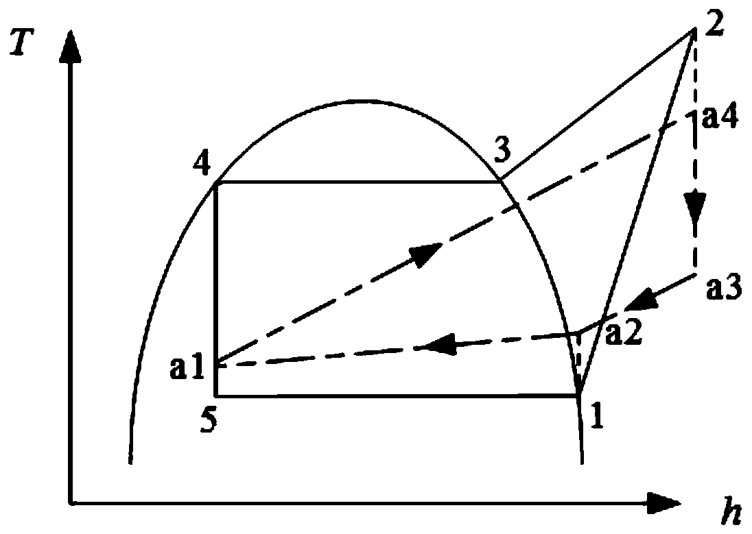
[0026] (1) If the system uses pure working fluid, the temperature and enthalpy diagram of the single-stage pure conventional heat pump drying system is as follows figure 2 shown.

[0027] The specific implementation is as follows:

[0028] The first step: the first-stage compressor 3 sucks the low-temperature and low-pressure working fluid at the outlet of the evaporator 2 working fluid side (such as figure 2 state "1"), compressing it into superheated gas at medium temperature and pressure (such as figure 2 state "2"). Afterwards, the superheated gas flows into the first-stage gas cooler 4 working medium side inlet, and the temperature of the working m...

specific Embodiment approach

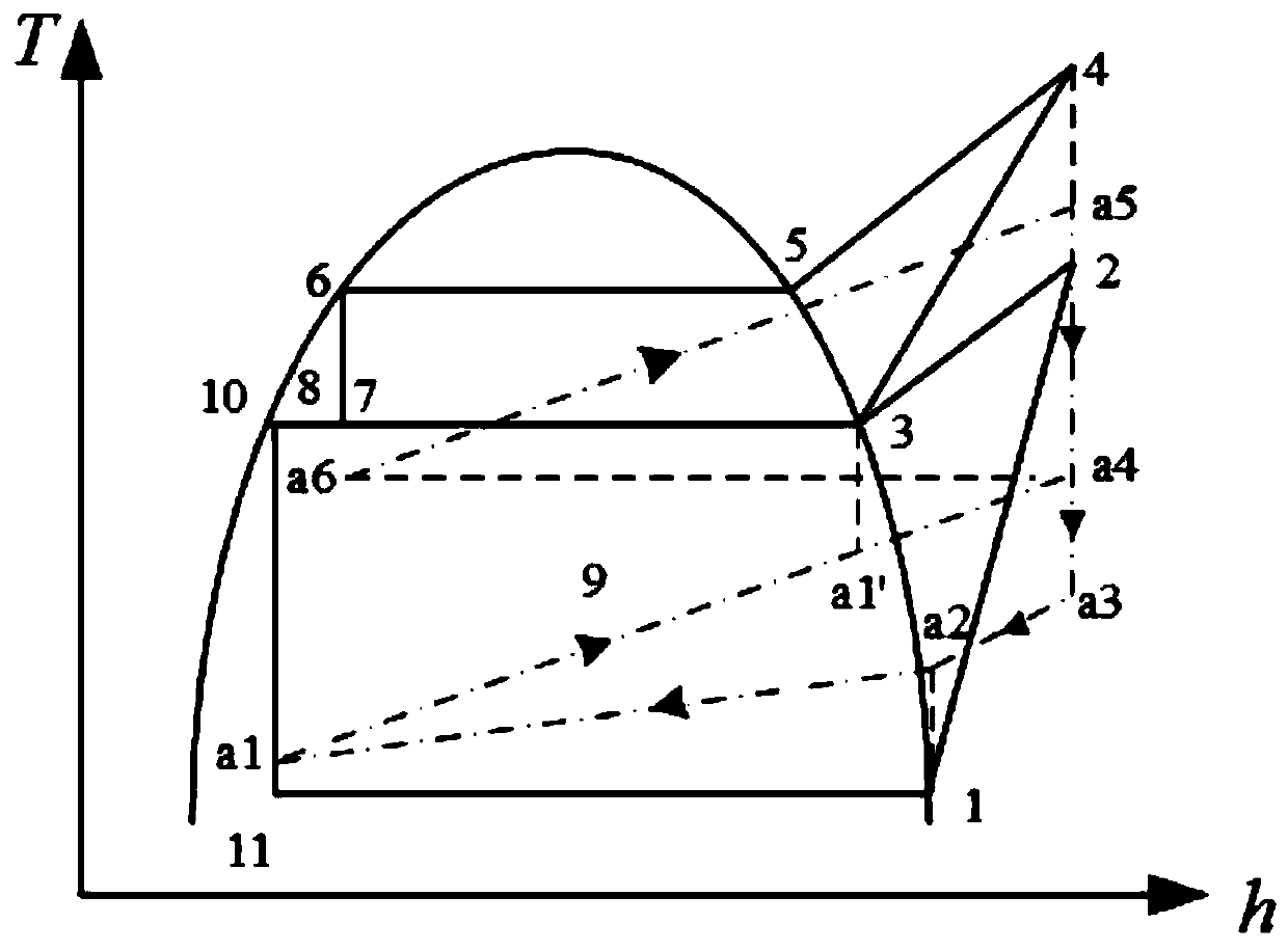
[0030] (2) If the system uses pure working fluid, the temperature and enthalpy diagram of the heat pump drying system with two-stage pure-compression double-condenser complete cooling in the middle is as follows image 3 shown. The specific implementation is as follows:

[0031] The first step: the first-stage compressor 3 sucks the low-temperature and low-pressure working fluid at the outlet of the evaporator 2 working fluid side (such as image 3 state "1"), compressing it into superheated gas at medium temperature and pressure (such as image 3 state "2"), then the superheated gas flows into the first-stage gas cooler 4 working medium side inlet, and the temperature of the working medium in the gas cooler 4 decreases after heat exchange (such as image 3 state "3"), then the gas is divided into two paths, and all the way flows into the first-stage condenser 5 to be condensed to saturated liquid (such as image 3 state "8"), and then the working fluid enters the first-stage...

Embodiment 2

[0041] Embodiment 2: A heat pump drying system with multiple condensers in the middle of three stages of compression and above is completely cooled.

[0042] This device can also be designed as a complete heat pump drying system in the middle of a multi-stage compression multi-stage condenser according to specific implementation needs, so as to realize multiple times of air drying, so as to better adapt to the drying process requirements of different materials. Specific examples of multi-stage compression multi-stage condenser intermediate complete heat pump drying system are as follows: Figure 5 .

[0043] The specific implementation is as follows:

[0044] Step 1: The first-stage compressor 3 sucks the low-temperature and low-pressure working fluid at the outlet of the working medium side of the evaporator 2, compresses it into superheated gas at intermediate pressure, and then enters the first-stage gas cooler 4 for heat exchange. After that, it is divided into two roads...


PUM


Abstract

The invention discloses a multistage compression multi-condenser intermediate complete cooling heat pump drying system which is composed of an evaporator, an air cooler, multiple stages of compressors, multiple stages of condensers, multiple stages of throttling valves and multiple stages of gas coolers. Materials are dewatered and dried according to technological requirements by arranging different numbers of stages, air is repeatedly continuously heated through multi-stage compression and multi-stage variable temperature condensation processes of working media, and irreversible loss caused by heat exchange between air and working media in the heating process can be remarkably reduced. The compression ratios of the multiple stages of compressors are small, non-azeotropic mixed working media with reasonable temperature slip can be adopted, the working media and air form good temperature matching, the heat transfer temperature difference can be further reduced, heat transfer irreversible loss of the condensers and the evaporator is reduced, and system energy efficiency is improved.

Description

technical field [0001] The invention relates to the technical field of heat pumps, in particular to a multi-stage compression multi-condenser intermediate complete cooling heat pump drying system. Background technique [0002] Drying is a process widely used in the production and processing of agricultural products. Drying accounts for a high proportion of industrial energy consumption, and the use of heat pump technology to dry agricultural products can save energy. At present, heat pump drying technology has been widely used in wood, tobacco, food and vegetable dehydration and other fields. Further improving the energy efficiency of heat pump drying equipment has important practical significance and social value for promoting energy saving and emission reduction and improving economic benefits. [0003] The condensing temperature of the conventional heat pump drying system is constant, the air is directly heated in the condenser, and the temperature difference between th...

Claims


Application Information

Patent Timeline
IPC IPC(8): F26B21/00F26B21/10F25B30/02F25B1/10F25B41/06F25B41/30
CPCF26B21/002F26B21/10F25B30/02F25B1/10F25B41/30
Inventor 代宝民赵谱赵晓璇漆乐孙悦桐刘笑
Owner TIANJIN UNIV OF COMMERCE
Why Eureka
Try Eureka