


Quick Research
Generate reliable direction feasibility study reports for your R&D in just a few steps.

Technical Q&A
Discover and master advanced knowledge NOW. Basics, ideas, possibilities, all at once.

Find Solutions
As an expert in R&D theories, this can generate solutions to your technical problems instantly.

Evaluate Feasibility
Analyze your overall solution with one click, know your potential R&D risks in advance.

Monitor Landscape
Get weekly tech updates, stay abreast of the latest tech innovations and key insights.
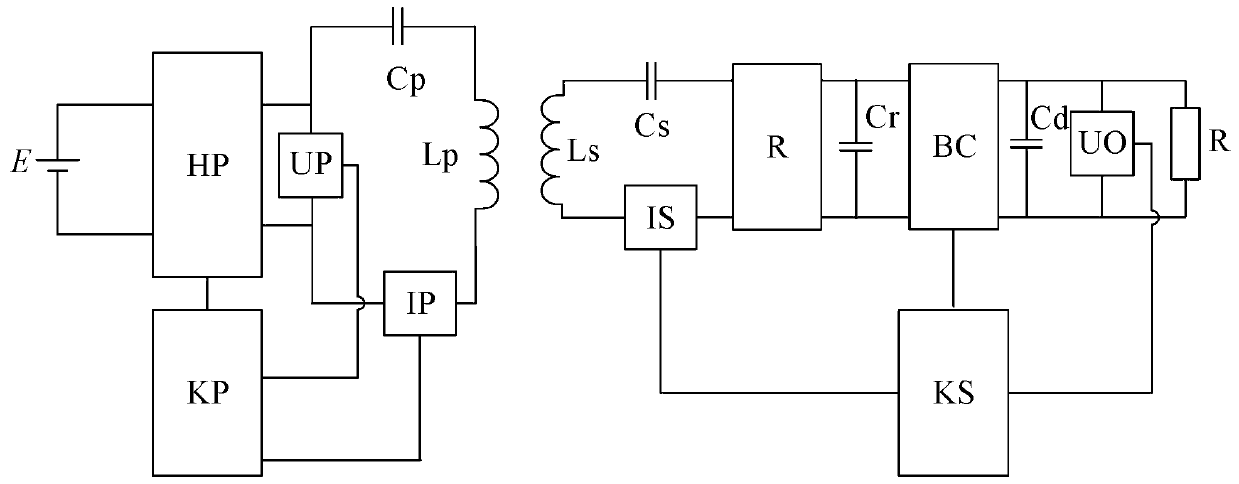
Dynamic wireless power transfer system control method
A wireless power transmission and control method technology, applied in electrical components, circuit devices, etc., can solve the problems of difficulty in ensuring the real-time requirements of the control system and the inability to guarantee the constant output power of the wireless power transmission system, so as to reduce complexity and improve Applicability, reducing the effect of mutual inductance measurement modules
- Summary
- Abstract
- Description
- Claims
- Application Information
AI Technical Summary
Problems solved by technology
Method used
Image

Examples
Embodiment approach
[0051] As a preferred embodiment of the present invention, in step 4, the specific method for estimating the mutual inductance M of the current transmitting coil and the pickup coil is as follows:
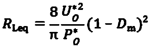
[0052] Note that the equivalent load resistance at the receiving end viewed from the input end of the rectifier R is RLeq. According to the preset output power PO* and output voltage UO* of the system, it can be expressed as:
[0053]
[0054] The reflection impedance ZR of the receiving end at the transmitting end can be expressed as:
[0055]
[0056] Among them, XS is the equivalent impedance of the coil self-inductance LS at the receiving end and the resonant capacitor CS at the receiving end;
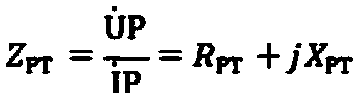
[0057] Then the inverter output impedance ZPT can be expressed by M and RLeq as:
[0058]
[0059] According to the pre-set system parameters, a standard with query table. The table is precomputed for different M and RLeq. In this lookup table, the with with the actual...
PUM
 Abstract
Description
Claims
Application Information
 - R&D Engineer
- R&D Manager
- IP Professional
- Industry Leading Data Capabilities
- Powerful AI technology
- Patent DNA Extraction
Browse by: Latest US Patents, China's latest patents, Technical Efficacy Thesaurus, Application Domain, Technology Topic, Popular Technical Reports.
© 2024 PatSnap. All rights reserved.Legal|Privacy policy|Modern Slavery Act Transparency Statement|Sitemap|About US| Contact US: help@patsnap.com