Parallel magnetic circuit hybrid excitation reluctance motor system

A hybrid excitation and reluctance motor technology, applied in the direction of magnetic circuit, magnetic circuit rotating parts, magnetic circuit static parts, etc., can solve the problems of narrow magnetic field adjustment range, poor stator structure strength, and unsuitable for high-speed rotation.

Active Publication Date: 2021-02-02
HARBIN INST OF TECH
View PDF4 Cites 0 Cited by
  • Summary
  • Abstract
  • Description
  • Claims
  • Application Information

AI Technical Summary

Problems solved by technology

[0006] The invention aims to solve the problem that the rotor core is made of silicon steel sheets, which is not suitable for high-speed rotation; the rotor iron consumption is high and the no-load loss is large; the magnetic circuit permeability of the mixed excitation of the series magnetic circuit is small, the excitation current is large, and the magnetic field adjustment range is narrow; the stator The core is divided into lobes along the circumference, and the strength of the stator structure is poor
Parallel Magnetic Hybrid Excited Reluctance Motor Systems Now Available

Method used


Image

  • Parallel magnetic circuit hybrid excitation reluctance motor system
  • Parallel magnetic circuit hybrid excitation reluctance motor system
  • Parallel magnetic circuit hybrid excitation reluctance motor system

Examples


Embodiment 1

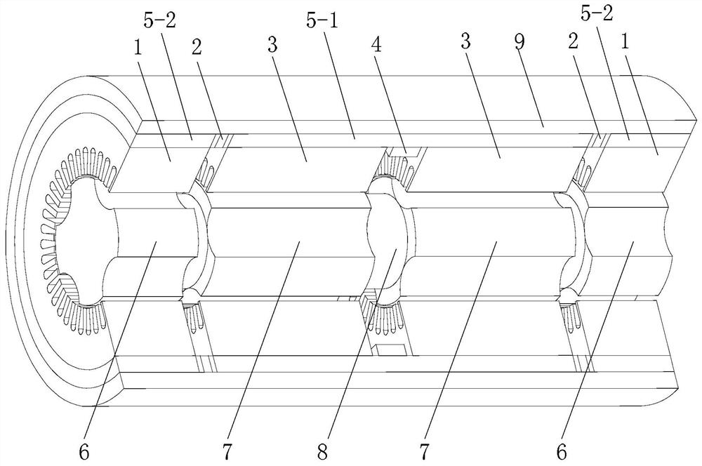
[0117] figure 1 A schematic structural diagram of the parallel magnetic circuit hybrid excitation reluctance motor system in Embodiment 1 is shown. refer to figure 1 , the parallel magnetic circuit hybrid excitation reluctance motor system of this embodiment includes a DC excitation power supply, a parallel magnetic circuit hybrid excitation reluctance motor and a power converter,

[0118] The output end of the DC excitation power supply is connected to the lead wire of the circular excitation coil unit 4 of the parallel magnetic circuit hybrid excitation reluctance motor; the armature winding lead wire of the parallel magnetic circuit hybrid excitation reluctance motor is connected to the AC end of the power converter; The parallel magnetic circuit hybrid excitation reluctance motor includes a stator and a rotor,

[0119] The stator is sleeved on the outer circumference of the rotor and there is an air gap between the stator and the rotor;

[0120] The stator includes k ...

Embodiment 2

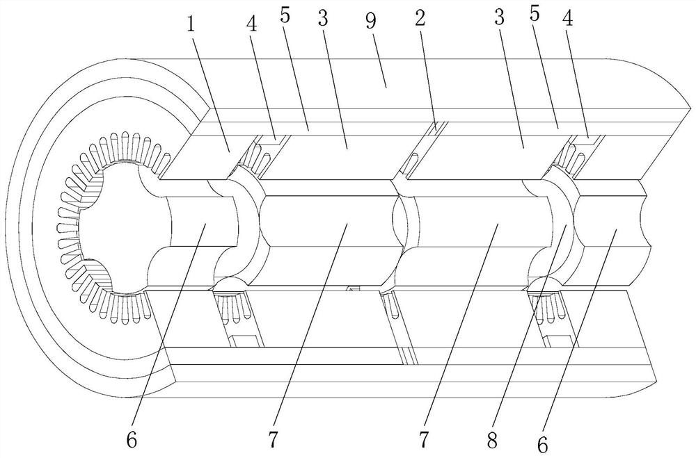
[0137] figure 2 A schematic structural diagram of the parallel magnetic circuit hybrid excitation reluctance motor system in Embodiment 2 is shown. refer to figure 2 , the parallel magnetic circuit hybrid excitation reluctance motor system of this embodiment includes a DC excitation power supply, a parallel magnetic circuit hybrid excitation reluctance motor and a power converter,

[0138] The output end of the DC excitation power supply is connected to the lead wire of the circular excitation coil unit 4 of the parallel magnetic circuit hybrid excitation reluctance motor; the armature winding lead wire of the parallel magnetic circuit hybrid excitation reluctance motor is connected to the AC end of the power converter; The parallel magnetic circuit hybrid excitation reluctance motor includes a stator and a rotor,

[0139] The stator is sleeved on the outer circumference of the rotor and there is an air gap between the stator and the rotor;

[0140] The stator includes k ...

Embodiment 3

[0157] Figure 4 A schematic structural diagram of the parallel magnetic circuit hybrid excitation reluctance motor system in Embodiment 3 is shown. refer to Figure 4 , the parallel magnetic circuit hybrid excitation reluctance motor system of this embodiment includes a DC excitation power supply, a parallel magnetic circuit hybrid excitation reluctance motor and a power converter,

[0158] The output end of the DC excitation power supply is connected to the lead wire of the circular excitation coil unit 4 of the parallel magnetic circuit hybrid excitation reluctance motor; the armature winding lead wire of the parallel magnetic circuit hybrid excitation reluctance motor is connected to the AC end of the power converter; The parallel magnetic circuit hybrid excitation reluctance motor includes a stator and a rotor,

[0159] The stator is sleeved on the outer circumference of the rotor and there is an air gap between the stator and the rotor;

[0160] The stator includes k ...


PUM


Abstract

A parallel magnetic circuit hybrid excitation reluctance motor system relates to the field of motors. The invention aims to solve the problem that the rotor core is made of silicon steel sheets, which is not suitable for high-speed rotation; the rotor iron consumption is high and the no-load loss is large; the magnetic circuit permeability of the mixed excitation of the series magnetic circuit is small, the excitation current is large, and the magnetic field adjustment range is narrow; the stator The core is divided into lobes along the circumference, and the strength of the stator structure is poor. In the present invention, a cylindrical permanent magnet excitation unit or a cylindrical permanent magnet excitation unit can generate a strong air gap density, the air gap magnetic field is evenly distributed along the axial direction, and the stator core loss is small; by arranging a circular excitation coil unit to adjust the air-gap magnetic field, the air-gap magnetic field is simple to adjust, and the adjustment range is large; the parallel magnetic circuit hybrid excitation reluctance motor of this application can be used as a motor or a generator, and can be operated as a motor, with large starting torque, constant The advantages of wide range of power speed regulation.

Description

technical field [0001] The invention relates to a parallel magnetic circuit hybrid excitation reluctance motor system, which belongs to the field of motors. Background technique [0002] The air gap magnetic density of the hybrid excitation motor is jointly generated by the permanent magnet and the electric field winding, and the magnetic field change required for speed (or voltage) adjustment is partially realized by the auxiliary electric field winding. When the direction of the electric excitation magnetic field is the same as that of the permanent magnetic field, the air gap magnetic field is strengthened; when the electric excitation magnetic field is in the opposite direction to the permanent magnetic field, the air gap magnetic field is weakened. Therefore, by adjusting the magnitude and direction of the electric excitation winding current, not only the field weakening control of the motor field can be realized, but also the field increase control can be realized. Th...

Claims


Application Information

Patent Timeline
Patent Type & Authority Patents(China)
IPC IPC(8): H02K19/12H02K1/14H02K1/17H02K3/04H02K1/24
CPCH02K1/146H02K1/17H02K1/246H02K3/04H02K19/12H02K2201/03
Inventor 寇宝泉赵元胜张浩泉
Owner HARBIN INST OF TECH
Why Eureka
Try Eureka