Method for measuring micro vibration in the optical axis of remote sensing satellite camera

A remote sensing satellite and measurement method technology, applied in the field of spacecraft measurement and control, can solve the problems of remote sensing satellite camera optical axis micro-vibration monitoring, short duration of micro-vibration measurement, limited reliability, etc., so as to improve design accuracy and improve system performance. Reliability and the effect of improving measurement accuracy

Active Publication Date: 2019-11-29
BEIJING RES INST OF SPATIAL MECHANICAL & ELECTRICAL TECH
View PDF18 Cites 3 Cited by
  • Summary
  • Abstract
  • Description
  • Claims
  • Application Information

AI Technical Summary

Problems solved by technology

[0005] The technical problem of the present invention is: to overcome the deficiencies of the prior art, to provide a remote sensing satellite camera optical axis micro-vibration measurement method to solve the existing remote sensing satellite system micro-vibration measurement duration is short, the reliability is limited and cannot The problem of direct monitoring of optical axis microvibration of remote sensing satellite camera

Method used


Image

  • Method for measuring micro vibration in the optical axis of remote sensing satellite camera
  • Method for measuring micro vibration in the optical axis of remote sensing satellite camera
  • Method for measuring micro vibration in the optical axis of remote sensing satellite camera

Examples


Embodiment Construction

[0045] The present invention will be described in detail below in conjunction with the accompanying drawings and specific embodiments.

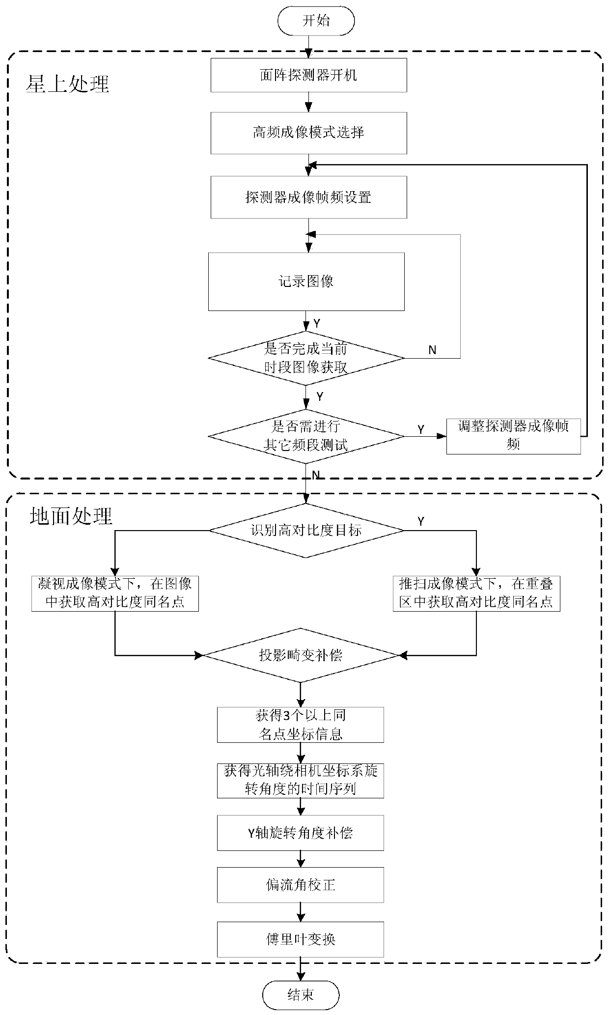
[0046] Such as figure 1 As shown, a remote sensing satellite camera optical axis micro-vibration measurement method involves a remote sensing satellite camera optical axis information sensitive method, which solves the optical axis deviation introduced by remote sensing satellite cameras due to factors such as satellite platform interference, installation errors, and environmental conditions. The problem of measurement of displacement, and the problem of image quality attenuation brought along with it. The method includes the following steps:

[0047] (1), obtain two consecutive frames of images including the same scene captured by the remote sensing satellite camera;

[0048] The remote sensing satellite camera is an area array camera. When the area array camera is turned on, you can select the area array high-frequency imaging mode and s...


PUM


Abstract

The invention provides a method for measuring micro vibration in the optical axis of a remote sensing satellite camera. The method comprises the following steps: (1) acquiring two continuous frames ofimages which are shot by the remote sensing satellite camera and contain the same scene; (2) identifying N homonymous points in the same scene in the two continuous frames of images, acquiring coordinates of each homonymous point in an image coordinate system, and N being greater than or equal to 3; (3) constructing an optical axis disturbance equation set based on the three-axis rotation angle of the optical axis around the camera coordinate system and the coordinates of each homonymous point of the two continuous frames of images in the image coordinate system in the imaging process of thetwo continuous frames of images; and (4) resolving the optical axis disturbance equation set to obtain the three-axis rotation angle of the optical axis around the camera coordinate system, and compensating the three-axis rotation angle of the optical axis around the camera coordinate system. According to the invention, optical axis position change information is directly acquired, and the measurement precision is improved.

Description

technical field [0001] The invention discloses a method for measuring optical axis micro-vibration of a remote sensing satellite camera, belonging to the field of spacecraft measurement and control. Background technique [0002] In order to achieve the best imaging effect of the remote sensing satellite camera, it is necessary to ensure that the optical axis of the camera is consistent with the design on the ground after entering orbit, which needs to be realized through a large number of experimental verification and flight state simulation. However, it is difficult to measure and compensate for the optical axis disturbance caused by the vibration interference of the satellite platform during the orbiting operation. Therefore, it is particularly important to measure the optical axis micro-vibration of the remote sensing satellite camera in real time on-orbit to restore the image quality of the remote sensing camera. [0003] The current on-orbit measurement methods of micr...

Claims


Application Information

Patent Timeline
Patent Type & Authority Applications(China)
IPC IPC(8): G01H9/00
CPCG01H9/00
Inventor 王芸刘涌胡永力刘晓鹏朱志豪梅强蔡浩孙欣魏久哲李恺王劲强王茫茫
Owner BEIJING RES INST OF SPATIAL MECHANICAL & ELECTRICAL TECH
Why Eureka
Try Eureka