Hybrid high-voltage direct-current circuit breaker based on bidirectional current limiting module

A current-limiting module and high-voltage direct current technology, applied in emergency protection circuit devices, circuit devices, emergency protection circuit devices, etc. for limiting overcurrent/overvoltage, can solve the problem of not distinguishing between overcurrent and short circuit, and false triggering of DC circuit breakers High requirements for devices and power devices, to achieve the effect of reducing the number of parallel connections, avoiding misoperation, and small amplitude

Active Publication Date: 2019-11-29
SOUTHWEST JIAOTONG UNIV
View PDF5 Cites 5 Cited by
  • Summary
  • Abstract
  • Description
  • Claims
  • Application Information

AI Technical Summary

Problems solved by technology

[0004] ABB and some other companies have produced hybrid DC circuit breakers that can cut off large currents, but in order to break DC fault currents with large amplitudes, the requirements for power devices are relatively high, and many power devices need to be connected in series and parallel. relatively high cost
Most of the loads in the DC power supply system are connected in parallel with filter capacitors for filtering. When the capacitor is first connected to the power supply system, the capacitor is charged, which will cause the current of the power supply line to rise instantaneously, which may accidentally trigger the DC circuit breaker, causing the circuit breaker to malfunction. action
Most existing DC circuit breakers do not have the ability to distinguish between overcurrent and short circuit

Method used


Image

  • Hybrid high-voltage direct-current circuit breaker based on bidirectional current limiting module
  • Hybrid high-voltage direct-current circuit breaker based on bidirectional current limiting module
  • Hybrid high-voltage direct-current circuit breaker based on bidirectional current limiting module

Examples


Embodiment Construction

[0031] The present invention will be further described below in conjunction with the accompanying drawings and specific embodiments.

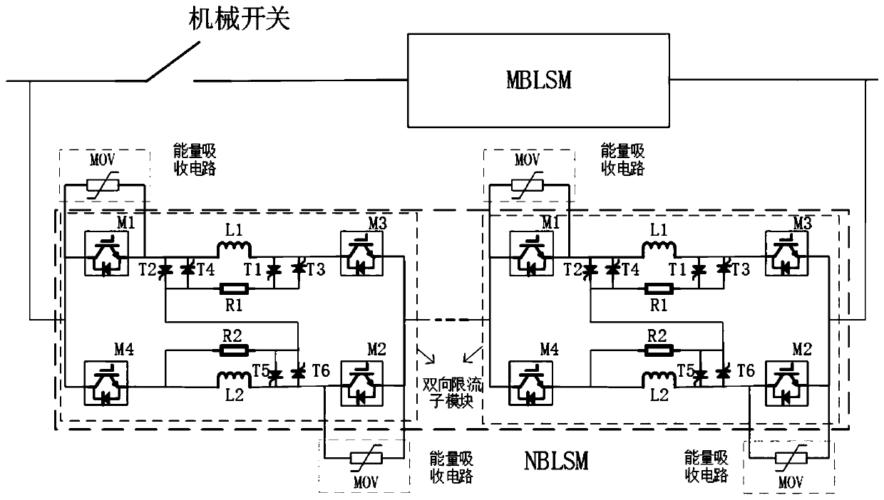
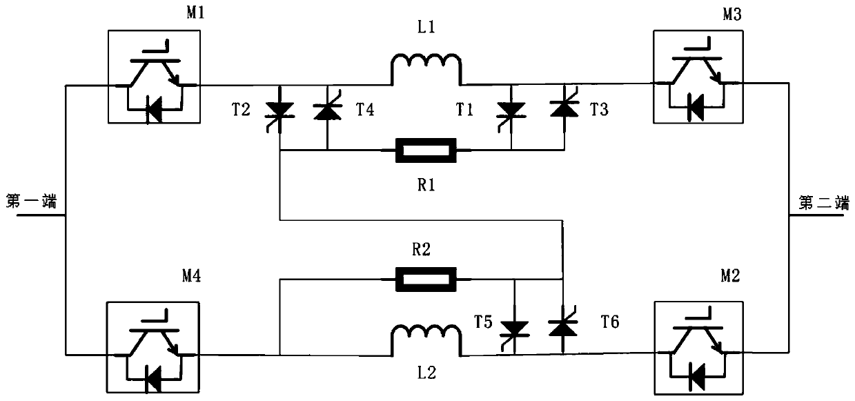
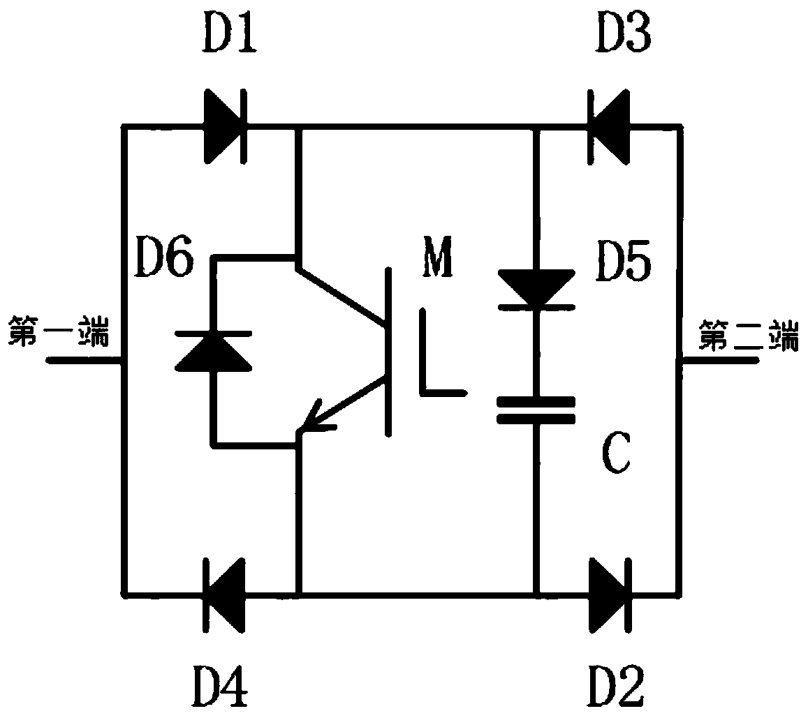
[0032] The structure of the present invention is as figure 1 As shown, it includes the flow branch and the fault removal branch connected in parallel; the flow branch includes mechanical switches connected in series and m bidirectional current limiting sub-modules (MBLSM); the fault removal branch includes n bidirectional Current-limiting sub-module (NBLSM), m1 , current limiting inductance L 1 and power electronics module M 3 ; The second current-limiting branch includes sequentially connected power electronic modules M 4 , current limiting inductance L 2 and power electronics module M 2 ; Power electronics module M 1 The first terminal and the power electronics module M 4 The first end of is connected to the first end of the bidirectional current limiting sub-module, the power electronic module M 3 The second terminal and the power ele...


PUM


Abstract

The invention discloses a hybrid high-voltage direct-current circuit breaker based on a bidirectional current limiting module, which comprises a through-current branch and a fault removal branch connected in parallel, wherein the through-current branch comprises a mechanical switch and m bidirectional current limiting sub modules which are connected in series with each other; the fault removal branch comprises n bidirectional current limiting sub modules which are connected in series, and m is smaller than n; the bidirectional current limiting sub module comprises a first current limiting branch and a second current limiting branch; the first current limiting branch comprises a power electronic module M1, a current limiting inductor L1 and a power electronic module M3 which are sequentially connected in series; and the second current limiting branch comprises a power electronic module M4, a current limiting inductor L2 and a power electronic module M2 which are sequentially connected in series. The requirement for the over-current capability is low, reliable turn-off of the power device can be guaranteed, the number of the power devices connected in parallel can be correspondinglyreduced, and the cost is reduced; and the amplitude of the switched-off fault current is small, the technical requirement on the circuit breaker is lower, and meanwhile, the damage of the fault current to the power supply system is smaller.

Description

technical field [0001] The invention relates to the technical fields of electrical equipment and electrical engineering, in particular to a hybrid high-voltage direct current circuit breaker based on a bidirectional current limiting module. Background technique [0002] High-voltage DC circuit breakers are key equipment for cutting off line faults and are crucial to maintaining the safe operation of DC power grids. Due to the low line impedance of the DC transmission system, when a short-circuit fault occurs on the line, the fault current rises quickly and has a high amplitude. The DC circuit breaker is required to respond quickly and have a large breaking current amplitude. In addition, compared with the AC transmission system, the DC transmission system is unipolar, and the current has no zero-crossing point, so the breaking principle of the AC circuit breaker cannot be applied. It is necessary to manually create the zero-crossing point to realize the current breaking, whi...

Claims


Application Information

Patent Timeline
Patent Type & Authority Applications(China)
IPC IPC(8): H02H3/087H02H9/02
CPCH02H3/087H02H9/02
Inventor 杨平张飞虎孔倩彭宇圣吴松荣
Owner SOUTHWEST JIAOTONG UNIV
Why Eureka
Try Eureka