

A Fast Boost Charge Pump System for Large Capacitors
A technology of boosting charge pump and capacitor, which is applied in the direction of conversion equipment without intermediate conversion to AC, can solve the problem of long voltage settling time, and achieve the effect of slow boosting speed and reducing settling time.
- Summary
- Abstract
- Description
- Claims
- Application Information
AI Technical Summary
Problems solved by technology
Method used
Image

Examples
Embodiment Construction
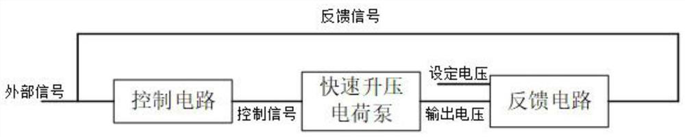
[0019] In this example, if figure 1 As shown, a fast boost charge pump system suitable for large capacitors includes: control circuit, boost charge pump and feedback circuit;
[0020] After receiving the external signal, the control circuit generates a high-level control signal CTL_H or a low-level control signal CTL_L in the current cycle and transmits it to the boost charge pump;
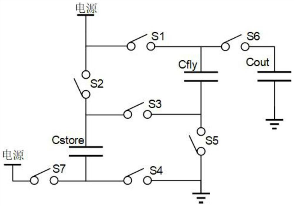
[0021] If the charge pump receives the high-level control signal CTL_H, the power supply in the boost charge pump charges the flying lead capacitor Cfly and the storage capacitor Cstore;
[0022] If the charge pump receives the low-level control signal CTL_L, the flying lead capacitor Cfly and the storage capacitor Cstore in the boost charge pump charge the output capacitor Cout and generate an output voltage VOUT to the feedback circuit;
[0023] After receiving the output voltage VOUT, the feedback circuit compares it with the set voltage value VREF:
[0024] If the output voltage VOUT is high...
PUM
 Abstract
Description
Claims
Application Information