A hanging structure for seat foam

A foam and seat technology, which is applied in vehicle seats, chairs, applications, etc., can solve the problems of poor bonding force between the suspending wire and the foam, complex foam modeling, restricted modeling and skeleton layout, etc. Achieve the effect of solving the problem of wire drawing force, reducing the number of magnets for positioning, and saving production management costs

Active Publication Date: 2022-06-21
YANFENG ADIENT SEATING CO LTD
View PDF0 Cites 0 Cited by
  • Summary
  • Abstract
  • Description
  • Claims
  • Application Information

AI Technical Summary

Problems solved by technology

[0004] 1. The existing foaming shape is complicated, and the number and types of outsourcing parts that need to be placed during production are large, which affects the production cycle and production efficiency
[0005] 2. The embedded steel wires are stacked on the material rack, and the steel wire heads are often hinged together, which makes it difficult to divide the materials in production
[0006] 3. The binding force between the hanging steel wire and the foam body is poor, and the steel wire is easy to pull off from the foam body when repairing and covering
[0007] 4. Surface treatment of foamed embedded steel wire, such as galvanized or blackened, which causes cost increase
[0008] 5. The number of magnetic powder sheets used to strengthen the positioning of the cloth during foam production increases the cost
[0009] 6. Some thin and thin seats are limited by the shape and skeleton layout, and there is not enough space for layout and design according to the traditional hanging structure
[0010] 7. For the insufficient thickness of the local area of ​​the foam body, there is not enough space to design the hanging structure. The existing technology will increase the bending of the steel wire, or use other connection methods such as shortening the length of the hanging steel wire and adding bristle belts, resulting in increased costs.
[0011] 8. The use of independent space special-shaped steel wire needs to consider anti-rotation and error prevention. Adding anti-rotation and error-proof limit structures will increase the complexity of the mold structure and the man-hours of mold processing

Method used


Image

  • A hanging structure for seat foam
  • A hanging structure for seat foam
  • A hanging structure for seat foam

Examples


Embodiment Construction

[0106] The present invention will be further described below in conjunction with the accompanying drawings and specific embodiments.

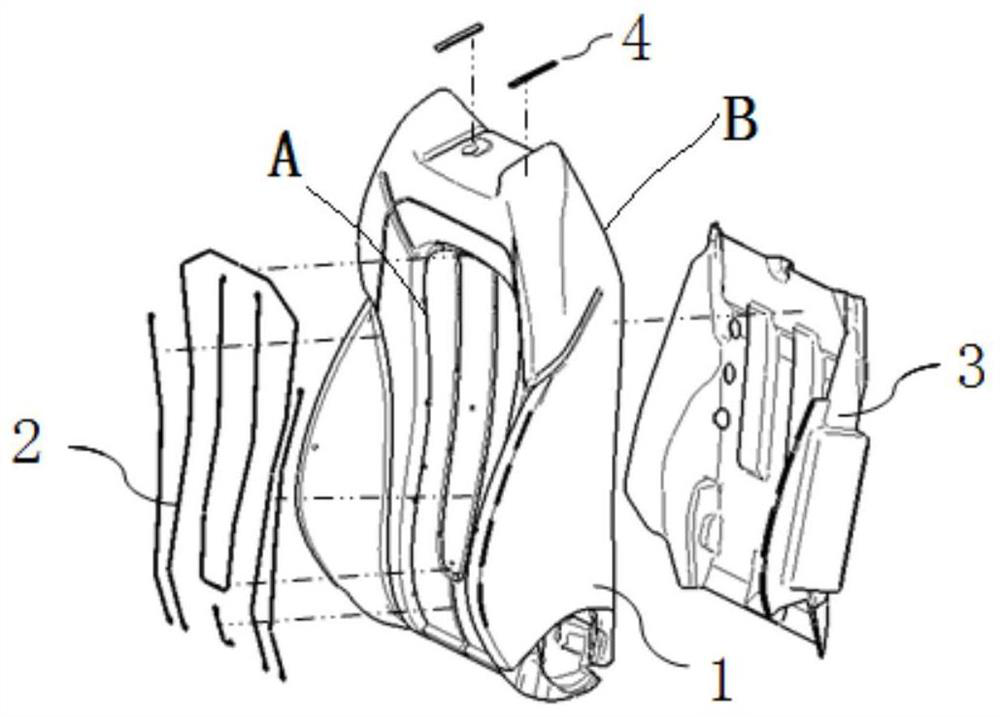
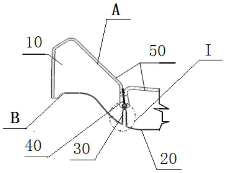
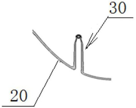
[0107] see figure 2 and image 3 , a suspending structure for seat foam shown in the figure, including foam 10 and reinforcing cloth 20. The suspending structure 30 is directly arranged on the side B of the reinforcing cloth 20 facing the foam body 10 and corresponds to the fixing point of the surface cover 50 . The suspending structure 30 tightens the surface covering 50 located on the surface A of the foamed body 10 through the surface covering tensioning structure 40.

[0108] see Figure 4 In the foaming process of the seat cushion of the traditional scheme, the cushion steel wire 2a is on the A side of the seat cushion foam body 1a, the seat cushion reinforcement cloth 3a is on the B side of the seat cushion foam body 1a, and the cushion steel wire 2a and the seat cushion reinforcement cloth 3a are independent of each other. In the pr...


PUM


Abstract

A hanging structure for seat foam disclosed by the present invention includes a foam and a reinforcing cloth, and is characterized in that the hanging structure is directly arranged at the position corresponding to the hanging of the reinforcing cloth and is connected with the The above reinforcement fabric connection. The inventive hanging structure simultaneously satisfies the two functional requirements of strengthening the surface B of the foam body and hanging the appearance of the surface A. The novel hanging structure of the present invention can save design space, realize light and thin shape hanging, realize light weight, improve foaming pull-off strength and optimize foaming production process.

Description

technical field [0001] The present invention relates to the technical field of seat preparation, in particular to a suspending structure for seat foam. Background technique [0002] The current seat foam structure can be found in figure 1 , the A-side inserts of the foam body 1 such as steel wire 2 and the thorn belt 4, and the B-side inserts of the foam body 1 such as reinforcing cloth 3 (some also have reinforcing blocks, supporting steel wires, and hanging wires) are all It is a part of independent structure, which is fixedly placed in the foaming mold during production and combined through the foaming process. [0003] This seat foam structure will encounter the following problems during production: [0004] 1. The existing foaming model is complex, and the number and types of external parts that need to be placed during production are many, which affects the production rhythm and production efficiency. [0005] 2. The embedded steel wire is stacked on the material ra...

Claims


Application Information

Patent Timeline
Patent Type & Authority Patents(China)
IPC IPC(8): B29C44/12B29L31/44
CPCB29C44/12B29L2031/443B29C44/1271B29C44/14B29L2031/58B29L2031/771B60N2/585B60N2/5891B60N2/5825B60N2/7041A47C7/029
Inventor 刘燕飞许伟唐任张杨马文辉
Owner YANFENG ADIENT SEATING CO LTD
Why Eureka
Try Eureka