Small-flux gas supply circular stirring anaerobic reaction method and reactor

An anaerobic reactor and circulating stirring technology, which is applied in the field of water treatment, can solve the problems of large gas flux and unresolved sludge properties, etc., and achieve the effect of improving removal effect and mass transfer

Pending Publication Date: 2019-12-03
恩格拜(武汉)生态科技有限公司
View PDF0 Cites 3 Cited by
  • Summary
  • Abstract
  • Description
  • Claims
  • Application Information

AI Technical Summary

Problems solved by technology

At present, the industry has developed an aeration device to be used as an agitator in the reactor, and the water body is distur

Method used


Image

  • Small-flux gas supply circular stirring anaerobic reaction method and reactor
  • Small-flux gas supply circular stirring anaerobic reaction method and reactor
  • Small-flux gas supply circular stirring anaerobic reaction method and reactor

Examples


application example 1

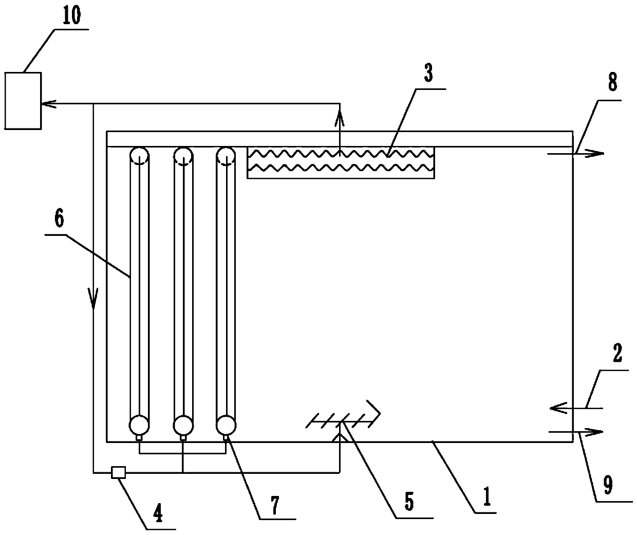
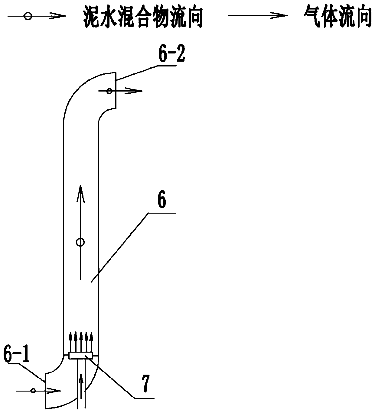
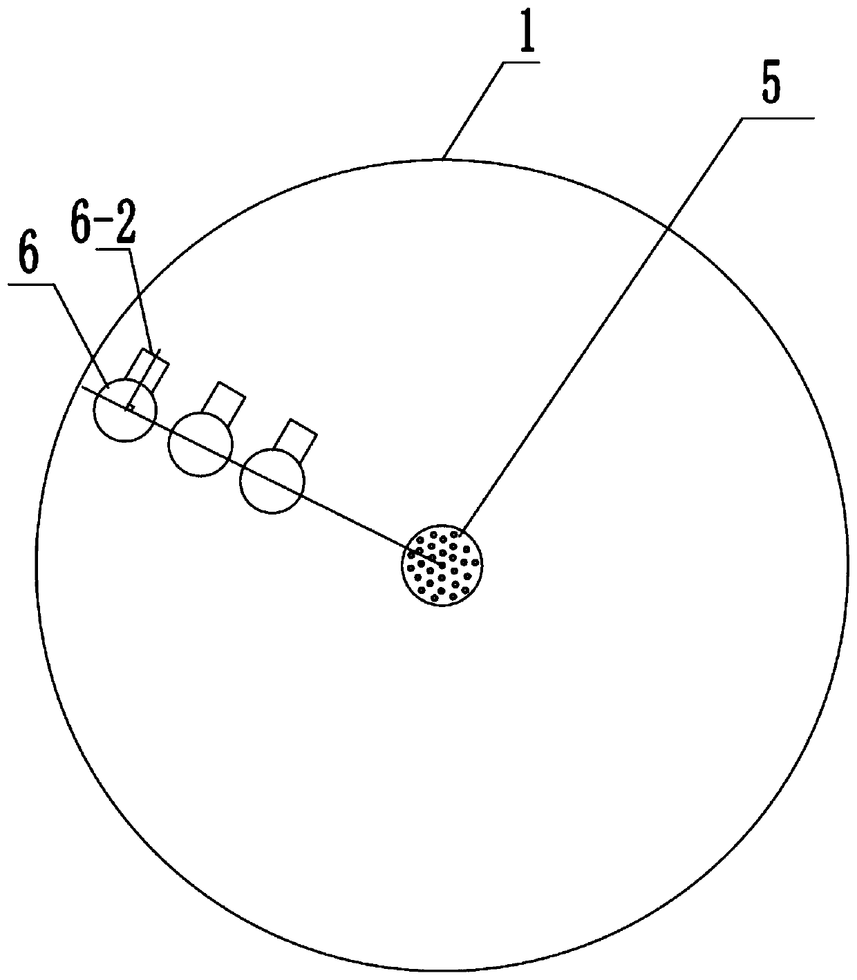
[0044] A small kitchen recycling device collects kitchen waste and kitchen waste from a community, about 8 tons per day. The recycling device is equipped with a solid crushing and extrusion device. The extruded liquid after extrusion needs to be treated on site and cannot be discharged directly. Squeeze liquid COD is 40000mg / L, design anaerobic reactor 100m of the present invention 3 A circular tank with a diameter of 6m and a height of 4.5m; three sets of airlift tubes of D100, distributed along the radial direction of the anaerobic reactor, close to the tank shell 1m, the distance between two adjacent sets of airlift tubes The diameter is 0.4m; the middle bottom of the anaerobic reactor is equipped with an aeration ring with a diameter of 300mm. This anaerobic reactor is used for the reaction, and about 20m of anaerobic sludge is added to the anaerobic reactor at startup. 3 , its water content is 80%, and it reaches a steady state after one month of operation. The effluent ...

application example 2

[0046] A pig farm with 30,000 pigs adopts the method of soaking manure in water, and produces a total of 300m of manure every day 3 , the manure is in the form of thin mud, with a solid content rate of 0.3%. It is necessary to use the anaerobic reactor of the present invention to degrade organic matter and produce biogas for power generation. Four anaerobic reactor tanks are designed, each with a diameter of 8m and a height of 5m. The semi-underground cement circular tank structure is adopted. Each tank is equipped with D400 central aeration plate and D200 airlift tube 3 groups. There is a biogas bladder on the top, equipped with a compressor. Biogas is produced every day and equipped with a generator, which can meet the electricity consumption of the pig farm. The effluent COD of the anaerobic reactor is less than 1000 mg / L, and it enters the downstream sewage plant for retreatment.


PUM


Abstract

The invention discloses a small-flux gas supply circular stirring anaerobic reaction method. The method comprises the following steps: adding sludge particles into an anaerobic reactor; and introducing sewage into the anaerobic reactor from a water inlet, mixing the sewage and the sludge particles, performing an anaerobic reaction, separating generated biogas through a three-phase separator, collecting part of the biogas through a biogas tank, pressurizing the other part of the biogas by a compressor, introducing the pressurized biogas into a gas stripping pipe and an aeration device, allowinga sludge-water mixture to enter the gas stripping pipe along the water flow direction, to be sprayed out from an outlet located in the top, and to return to the bottom in circular motion and a vortexshape, mixing the mixture with inlet water, and performing an anaerobic reaction circularly under the action of the aeration device. The method does not damage sludge flocs on the premise of improving the mud-water mixing effect, and has higher mass transfer efficiency and a high reaction rate, the COD removal rate of the sewage reaches 90% or above, and a device provided by the invention has a simple structure and low construction costs.

Description

technical field [0001] The invention relates to an anaerobic reaction method and a used reactor, belonging to the technical field of water treatment. Background technique [0002] As an important means of wastewater treatment, anaerobic biological treatment technology can remove high-concentration organic pollutants in water. The characteristics of anaerobic biological treatment technology, such as high removal load, easy operation control, low operating cost and small footprint, make it successfully applied in the environmental field. Anaerobic reactor is the core carrier of anaerobic biological treatment technology and an important place to maintain various anaerobic and facultative microbial activities. To date, various anaerobic reactors have been developed. [0003] The main factors affecting the efficiency of anaerobic reaction include mud-water mixing effect and sludge properties. The better the mixing effect of mud and water, the larger the contact area between mi...

Claims


Application Information

Patent Timeline
IPC IPC(8): C02F3/28
CPCC02F3/28C02F3/2866C02F3/2873
Inventor 李明维克·恩格拜鄢紫
Owner 恩格拜(武汉)生态科技有限公司
Why Eureka
Try Eureka