High-yield and energy-saving mixing type lime kiln

A lime kiln and mixing technology, applied in the field of lime production, can solve the problems of resource waste, increase fuel consumption, prolong calcination time, etc., and achieve the effects of improving production efficiency, avoiding resource waste and reducing fuel consumption.

Pending Publication Date: 2019-12-03
四川马氏窑技术发展有限公司
View PDF0 Cites 4 Cited by
  • Summary
  • Abstract
  • Description
  • Claims
  • Application Information

AI Technical Summary

Problems solved by technology

[0005] The purpose of the present invention is to provide a high-yield lime kiln for the currently commonly used mixing type lime kiln, which does not distinguish according to the volume of raw materials during the material distribution process, resulting in prolonged calcination time, increased fuel consumption, and waste of resources. Energy-saving mixing lime kiln

Method used


Image

  • High-yield and energy-saving mixing type lime kiln
  • High-yield and energy-saving mixing type lime kiln
  • High-yield and energy-saving mixing type lime kiln

Examples


Embodiment 1

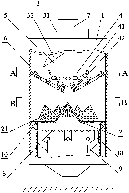
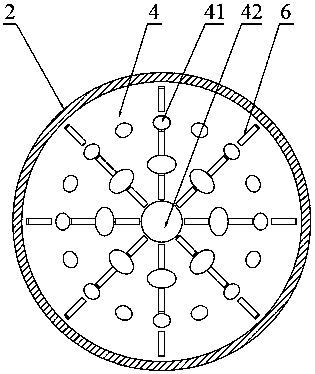
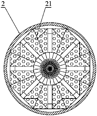
[0031] Such as Figure 1-3 As shown, the high-yield and energy-saving mixing type lime kiln includes a kiln body 1, a grate 2 is arranged inside the kiln body 1, a distribution mechanism 3 is arranged above the grate 2, and the distribution mechanism 3 and the grate 2 There is also a distribution plate 4 between them, and the distribution plate 4 is arranged obliquely. The lowest position of the inclined surface of the distribution plate 4 is set at the center of the distribution plate 4. In the kiln body 1, a large upper part and a smaller one are formed. The material distribution space 5 in the form of a hollow circular platform is provided with a number of through holes 41 for the passage of raw materials on the material distribution plate 4, and the through holes 41 gradually increase along the inclination direction of the material distribution plate 4.

[0032] In the high-yield and energy-saving mixing lime kiln of this embodiment, a material distribution plate 4 is arra...

Embodiment 2

[0039] Such as Figure 1-3 As shown, the structure of the high-yield and energy-saving mixing lime kiln of this embodiment is the same as that of Embodiment 1, the difference is that: the distribution plate 4 is also provided with a number of blocking blocks for blocking the movement of raw materials towards the discharge port 42 6.

[0040] In the high-yield and energy-saving mixing lime kiln of this embodiment, by setting the blocking block 6 on the material distribution plate 4, on the one hand, the moving speed of the raw material is slowed down, and the impact caused by the raw material falling into the grate 2 on the grate 2 is avoided, which affects the furnace. The stability of the raw materials laid on the grate 2, on the other hand, when the raw materials fall into the distribution plate 4, they are hit by the blocking block 6, and the volume is reduced, ensuring that the volume of the raw materials entering the grate 2 is relatively uniform, and further ensuring the...


PUM


Abstract

The invention relates to the field of lime production, in particular to a high-yield and energy-saving mixing type lime kiln. The high-yield and energy-saving mixing type lime kiln comprises a kiln body, a fire grate is arranged in the kiln body, a distributing mechanism is arranged above the fire grate, a dividing plate is further arranged between the distributing mechanism and the fire grate andobliquely arranged, a plurality of through holes used for passing of raw materials are formed in the dividing plate, the through holes are gradually enlarged in the oblique direction of the dividingplate, thus the raw materials guided into the kiln body by the distributing mechanism are screened by the dividing plate and then fall into the fire grate for calcination treatment, the raw materialsfalling onto the fire grate are treated distinctively according to the different sizes, large-size fuel and large-size limestone make contact, small-size fuel and small-size limestone make contact, the fuel and the limestone which make contact are adaptive in size, the calcination process is carried out smoothly and advantageously, the fuel consumption is decreased, waste of resources is avoided,and the production efficiency is improved.

Description

technical field [0001] The invention relates to the field of lime production, in particular to a high-yield and energy-saving mixing type lime kiln. Background technique [0002] As an important auxiliary material in industrial production, lime is widely used in many industries such as metallurgy, chemical industry, environmental protection, building materials, etc. At present, the commonly used mixing type lime kiln for preparing lime generally uses coal, coke and other solid fuels to calcinate limestone to prepare lime. The current mixing The type lime kiln generally adopts the structure of kiln top feeding and kiln bottom ash discharge. The fuel and limestone mixed together are introduced into the kiln body with a grate through the material distribution mechanism, and the fuel and limestone are thrown on the grate. Air is introduced into the lower side to maintain the combustion of the fuel and make the fuel calcined limestone to prepare lime. [0003] The material dis...

Claims


Application Information

Patent Timeline
Patent Type & Authority Applications(China)
IPC IPC(8): C04B2/12C04B2/02
CPCC04B2/02C04B2/12
Inventor 马寿春马强
Owner 四川马氏窑技术发展有限公司
Why Eureka
Try Eureka