Actual drilling simulation and drilling parameter testing device and method for nearly horizontal directional drilling

A technology of drilling parameters and horizontal orientation, applied in directional drilling, drilling equipment and methods, earthwork drilling, etc., can solve problems such as difficulties in test sites, inability to fully grasp geological conditions, inability to collect relevant parameters, etc., to improve monitoring Level and accuracy, direct observation is more convenient, and the effect of improving the test environment

Pending Publication Date: 2019-12-03
XIAN RES INST OF CHINA COAL TECH& ENG GROUP CORP
View PDF6 Cites 5 Cited by
  • Summary
  • Abstract
  • Description
  • Claims
  • Application Information

AI Technical Summary

Problems solved by technology

[0004] On-site tests for process and instrument development often have high requirements for the test site and need to be targeted. It is difficult to find a suitable test site
Secondly, field tests generally use actual production equipment and are constructed in natural geological bodies. The conditions of natural geological bodies vary greatly. Before the test, the accurate geological conditions cannot be fully grasped, and there is no condition to install monitoring instruments, and relevant parameters during the test cannot be collected. There is no basis for the evaluation and analysis of the test phenomenon, and the analysis of the test phenomenon cannot lock the influencing factors, and the repeatability of the test is poor.
In addition, field tests often run through the actual production of coal mines or engineering projects. Due to the constraints of coal mine production progress, there is not enough test time, the space underground in coal mines is small, and the requirements for explosion-proof equipment also limit some equipment, tools, and monitoring equipment. Instrument use

Method used


Image

  • Actual drilling simulation and drilling parameter testing device and method for nearly horizontal directional drilling
  • Actual drilling simulation and drilling parameter testing device and method for nearly horizontal directional drilling
  • Actual drilling simulation and drilling parameter testing device and method for nearly horizontal directional drilling

Examples


Embodiment

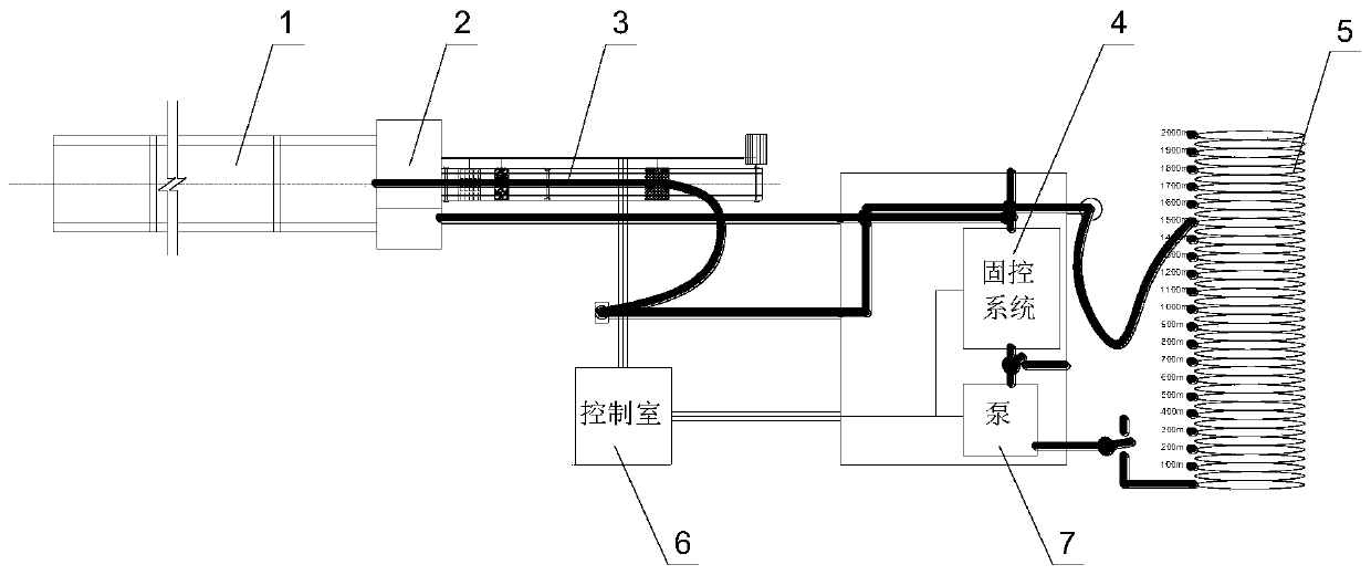
[0046] Such as figure 1 As shown, the near-horizontal directional drilling actual drilling simulation and drilling parameter test bench includes simulated geological body 1, drilling drive system 3, mud pump 7, solid control system 4, manifold system 5 and monitoring control system 66 part.

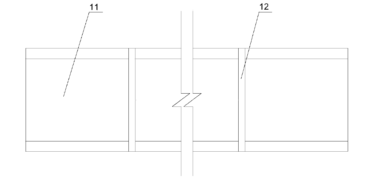
[0047] Such as figure 2 As shown, the simulated geological body is a concrete cylinder 11 fixed on the ground, which is assembled by multi-section prefabricated concrete cylinders. The length of the assembly is determined according to the test requirements. The axes are coincident, and the assembly gap 12 is poured with concrete of the same label as the concrete cylinder, so that it becomes a whole.

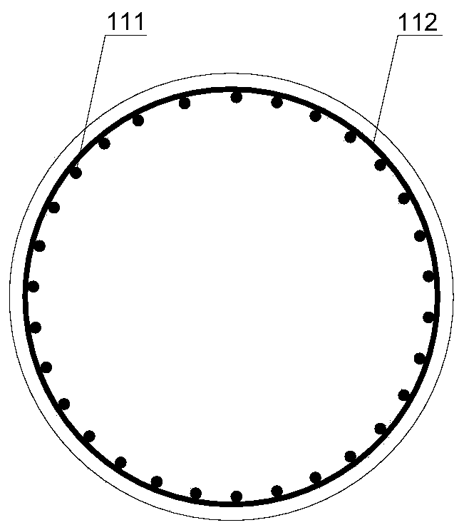
[0048] Such as image 3As shown, in order to ensure the strength and integrity of the concrete block so that it does not crack during drilling, the concrete cylinder is respectively equipped with main reinforcement 111 and stirrup 112, and the drilling track is arranged in the concrete w...


PUM


Abstract

The invention discloses an actual drilling simulation and drilling parameter testing device and method for nearly horizontal directional drilling. The actual drilling simulation and drilling parametertesting device comprises six parts of a simulated geological body, a drilling drive system, a mud pump, a solid control system, a manifold system and a monitoring control system. A horizontally disposed concrete cylinder is utilized to simulate the real drilling geological body, tracks are laid in the axis direction of the concrete cylinder, a power head installed on the tracks is driven by a chain to slide to simulate a drilling machine, drilling fluid circulation is realized through the solid control system, the mud pump and the manifold system, all parts of a test bed are controlled by themonitoring control system, and parameters in the drilling process are monitored. The test bed can provide a site and a platform for directional drilling process development, instrument testing and nearly horizontal directional drilling fundamental researches.

Description

technical field [0001] The invention relates to a real drilling simulation and parameter testing device, belonging to the field of directional drilling, in particular to a real drilling simulation and drilling parameter testing device and method for near-horizontal directional drilling. Background technique [0002] Underground directional drilling technology in coal mines can realize the precise control of the drilling trajectory, ensure the effective extension of the drilling trajectory in the predetermined layer, and increase the effective drainage distance of the drilling hole. In addition, directional drilling technology can carry out multi-branch hole construction, and the drilled holes can evenly cover the entire working face. It has become the main technical approach for high-efficiency gas drainage in coal mining areas in my country. [0003] As the working conditions of underground directional drilling construction in coal mines become more and more complex, and co...

Claims


Application Information

Patent Timeline
Patent Type & Authority Applications(China)
IPC IPC(8): E21B44/00E21B7/04E21B21/08
CPCE21B44/00E21B7/046E21B21/08
Inventor 李泉新陈盼刘建林许超曹明方俊
Owner XIAN RES INST OF CHINA COAL TECH& ENG GROUP CORP
Why Eureka
Try Eureka