Installation structure of compressor impeller

A compressor impeller and installation structure technology, which is applied to components, mechanical equipment, machines/engines, etc. of pumping devices used for elastic fluids, and can solve the problems of repeated assembly and disassembly limiting the application range of centrifugal refrigeration compressors, etc. , to achieve the effect of great practical value, easy popularization and application, and simple connection structure

Active Publication Date: 2019-12-03
QINGAN GRP
View PDF6 Cites 3 Cited by
  • Summary
  • Abstract
  • Description
  • Claims
  • Application Information

AI Technical Summary

Problems solved by technology

[0002] In traditional centrifugal refrigeration compressors, the connection method of the rotor is widely used in gear speed-up connection structure or coupling connection structure. The problem of centering, the complexity of parts and the repeatability of assembly and disassembly limit the application range of centrifugal refrigeration compressors.

Method used


Image

  • Installation structure of compressor impeller
  • Installation structure of compressor impeller

Examples


Embodiment 1

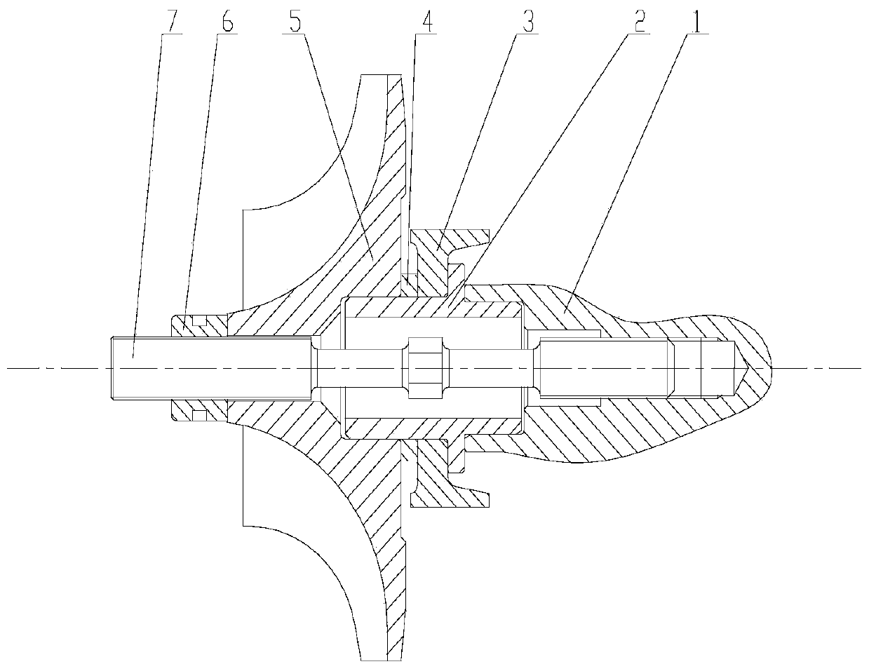
[0028] Example 1, such as figure 1 As shown, a compressor impeller installation structure is provided, including a motor rotor shaft 1, a transition sleeve 2, a center tie rod 7, an impeller 5, a compression nut 6, an adjustment pad 4 and a balance plate 3;

[0029] The shaft end of the motor rotor shaft has an axial step hole, the small hole of the step hole is an internal thread hole, and the large hole of the step hole is a positioning hole;

[0030] Both ends of the center tie rod have external threads, the threads at both ends have the same rotation direction, the external threads at one end are fastened with the internal thread holes of the motor rotor shaft, and the rotation direction of the external threads at one end is opposite to the rotation direction of the motor rotor shaft;

[0031] The transition bushing is set outside the center tie rod, and the outer diameter of one end of the transition bushing matches the inner diameter of the large hole, and is positioned ...

Embodiment 2

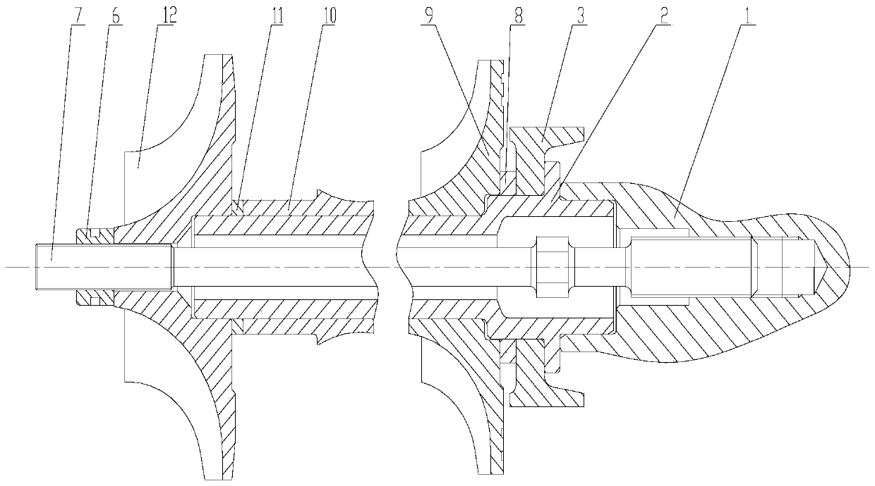
[0033] Example 2, such as figure 2 As shown, there is provided an installation structure for multi-stage impellers of a compressor, including a motor rotor shaft, a transition sleeve, a central tie rod, at least two impellers, at least one spacer sleeve, a compression nut, at least two adjustment pads and a balance plate; There is an adjusting pad and a spacer sleeve between the impellers of each stage;

[0034] The shaft end of the motor rotor shaft has an axial step hole, the small hole of the step hole is an internal thread hole, and the large hole of the step hole is a positioning hole;

[0035] Both ends of the center tie rod have external threads, the threads at both ends have the same rotation direction, the external threads at one end are fastened with the internal thread holes of the motor rotor shaft, and the rotation direction of the external threads at one end is opposite to the rotation direction of the motor rotor shaft;

[0036] The transition bushing is set o...


PUM


Abstract

The invention discloses a mounting structure of a compressor impeller. The mounting structure comprises a motor rotor shaft, a transition shaft sleeve, a central pull rod, an impeller, a compression nut, an adjusting pad and a balance disc, rotor parts such as a centrifugal impeller, a shaft sleeve, a balance disc and a transition shaft in the centrifugal refrigeration compressor are connected through a center pull rod, and pre-tightening force is applied through a pressing nut. In the working process of the centrifugal refrigeration compressor, torque is transmitted among all the rotor partsthrough plane friction, due to the action of proper pre-tightening force applied to the gland nut, the rotor can be normally connected and operated, looseness is avoided, and the safety stock of all the rotor parts is reduced. The application of the central pull rod connection and plane contact interface torque transmission structure forms a structure of the invention, and the structure is particularly suitable for connection between rotor parts in a centrifugal refrigeration compressor.

Description

technical field [0001] The invention belongs to the field of compressor impeller assembly, in particular to a compressor impeller installation structure. Background technique [0002] In traditional centrifugal refrigeration compressors, the connection method of the rotor widely adopts the gear speed-up connection structure or the coupling connection structure. The problem of centering, the complexity of parts and the repeatability of assembly and disassembly limit the application range of centrifugal refrigeration compressors. . The central tie rod connection structure is mostly used in modern turboprop and turboshaft engines. The rotor is mainly composed of a wheel disc and a central tie rod. The wheel disc and the wheel disc are connected by end teeth (Hess teeth), and each part is connected as a whole by a central tie rod, which connects the wheel discs in series. Stand up and be preloaded, the torque is transmitted through the face teeth and the actual load is taken. ...

Claims


Application Information

Patent Timeline
IPC IPC(8): F04D29/26F04D29/28F04D29/30F04D29/62F04D29/053
CPCF04D29/053F04D29/266F04D29/284F04D29/30F04D29/624
Inventor 肖立宁崔宁贤朱明正李伟伟陈颖君
Owner QINGAN GRP
Why Eureka
Try Eureka