Antenna module and electronic equipment

An antenna module and antenna technology, which is applied to antenna equipment with additional functions, antennas, resonant antennas, etc., can solve the problem of large antenna occupation, achieve the effect of saving occupied space and improving integration

Active Publication Date: 2019-12-03
VIVO MOBILE COMM CO LTD
View PDF4 Cites 21 Cited by
  • Summary
  • Abstract
  • Description
  • Claims
  • Application Information

AI Technical Summary

Problems solved by technology

[0003] Embodiments of the present invention provide an antenna module and electr

Method used


Image

  • Antenna module and electronic equipment
  • Antenna module and electronic equipment
  • Antenna module and electronic equipment

Examples


Embodiment Construction

[0029] The following will clearly and completely describe the technical solutions in the embodiments of the present invention with reference to the accompanying drawings in the embodiments of the present invention. Obviously, the described embodiments are some of the embodiments of the present invention, but not all of them. Based on the embodiments of the present invention, all other embodiments obtained by persons of ordinary skill in the art without creative efforts fall within the protection scope of the present invention.

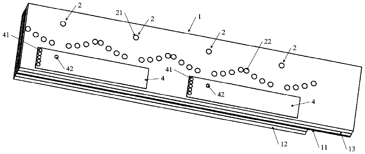
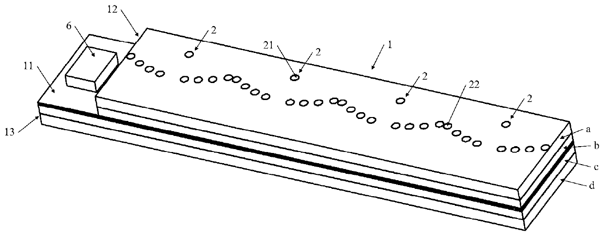
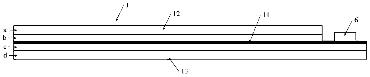
[0030] Such as Figure 1 to Figure 15 As shown, the embodiment of the present invention provides an antenna module, including:

[0031] The substrate 1, the substrate 1 includes a floor 11, a first dielectric layer 12 and a second dielectric layer 13, the first dielectric layer 12 and the second dielectric layer 13 are respectively located on both sides of the floor 11;

[0032] The millimeter-wave antenna array, the millimeter-wave antenna array incl...


PUM


Abstract

The invention provides an antenna module and electronic equipment. The antenna module comprises a substrate, a millimeter wave antenna array, a radio frequency integrated circuit and a non-millimeterwave antenna, wherein the substrate comprises a ground plate, a first dielectric layer and a second dielectric layer, and the first dielectric layer and the second dielectric layer are located at twosides of the ground plate respectively; the millimeter wave antenna array comprises N dipole antenna units, the N dipole antenna units are sequentially arranged on the substrate at intervals along thesubstrate, and N is an integer greater than 1; the radio frequency integrated circuit is arranged on the first dielectric layer, and the radio frequency integrated circuit is connected with the feeding structures of the N dipole antenna units; and the non-millimeter wave antenna is arranged on the second dielectric layer. Thus, the millimeter wave dipole antenna array and the non-millimeter waveantenna are integrally arranged, so that the integration level of the antenna module is improved, and the space occupied by the antenna is saved.

Description

technical field [0001] The invention relates to the technical field of antennas, in particular to an antenna module and electronic equipment. Background technique [0002] 5G (5th-Generation) is divided into two frequency bands, FR1 (Frequency Range 1, frequency band 1) covers a frequency range of 450MHz-7.125GHz, and FR2 (Frequency Range 2, frequency band 2) covers a frequency range of 24.25GHz-43GHz. Among them, FR1 is a non-millimeter wave frequency band, and FR2 is a millimeter wave (mmWave) frequency band. At present, the 5G non-millimeter wave antenna and the millimeter wave antenna are designed separately, which makes the overall antenna occupy a large volume. Contents of the invention [0003] Embodiments of the present invention provide an antenna module and electronic equipment to solve the problem that the existing antenna occupies a large volume. [0004] The present invention is achieved like this: [0005] In a first aspect, an embodiment of the present in...

Claims


Application Information

Patent Timeline
IPC IPC(8): H01Q23/00H01Q21/00H01Q1/48H01Q1/50
CPCH01Q23/00H01Q21/00H01Q1/48H01Q1/50H01Q19/17H01Q21/24H01Q1/523H01Q25/001H01Q1/2283H01Q9/16H01Q9/18H01Q9/0407H01Q9/285H01Q1/46H01Q21/0025
Inventor 黄奂衢简宪静马荣杰王义金
Owner VIVO MOBILE COMM CO LTD
Why Eureka
Try Eureka