
Plastic product cutting device

A cutting device and technology for plastic products, applied in the field of plastic product processing, can solve the problems of inability to clean, poor adjustment ability, etc., and achieve the effects of reducing work intensity, convenient cutting, and good practicability

Inactive Publication Date: 2019-12-06
界首市金科塑业有限公司
View PDF8 Cites 4 Cited by
  • Summary
  • Abstract
  • Description
  • Claims
  • Application Information

AI Technical Summary

Problems solved by technology

[0004] The purpose of the present invention is to provide a cutting device for plastic products, which solves the problem that the existing plastic product cutting equipment has poor adjustment ability and cannot be cleaned

Method used


Image

  • Plastic product cutting device
  • Plastic product cutting device
  • Plastic product cutting device

Examples


Embodiment 1

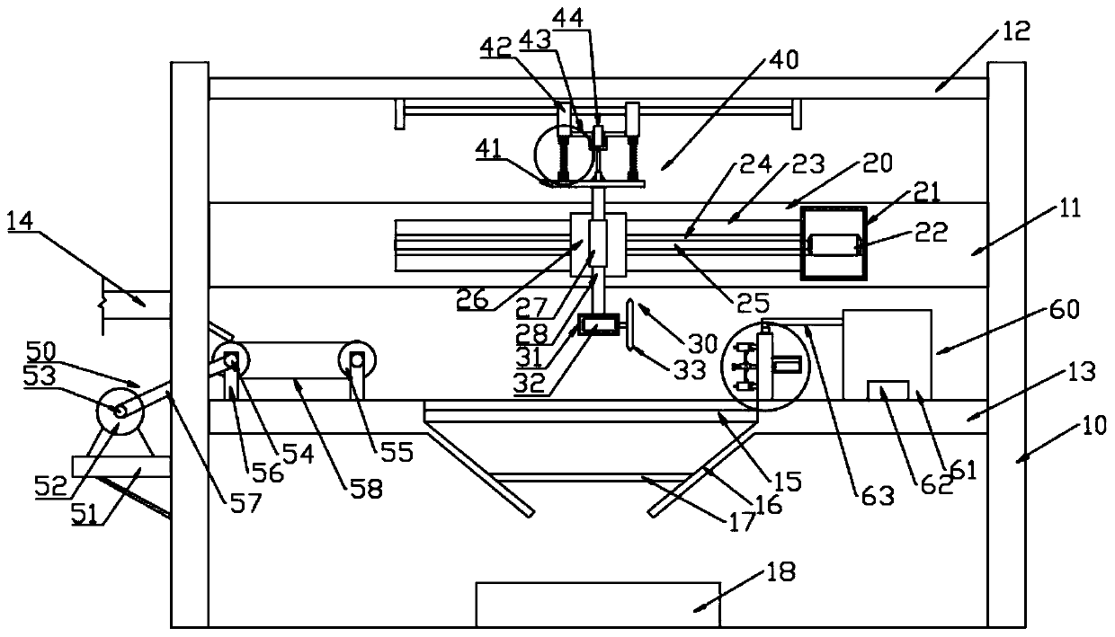
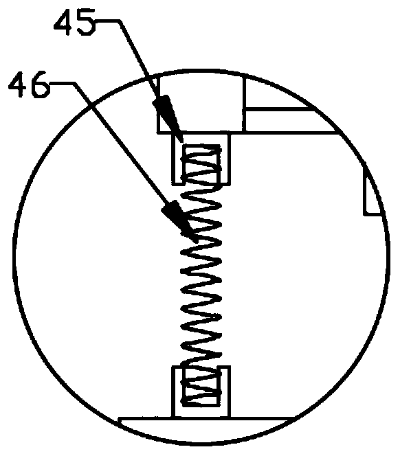
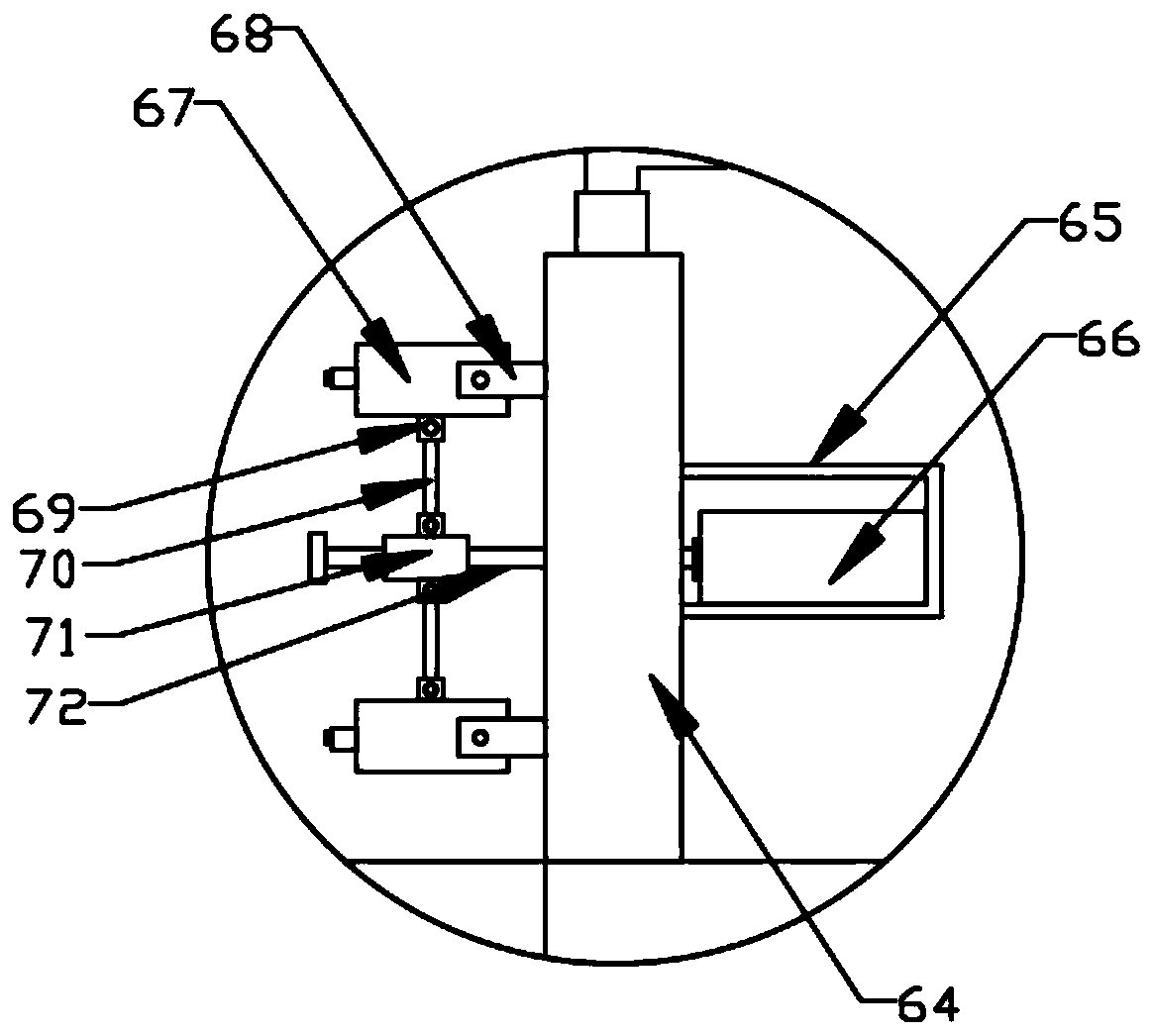
[0027] see Figure 1~4 , in an embodiment of the present invention, a cutting device for plastic products includes a vertical plate 10, a first fixed plate 11, a second fixed plate 12 and a cutting table 13 are fixed between the vertical plates 10, the first fixed plate 11 is used for The horizontal movement of the cutting assembly 30 is facilitated, the second fixing plate 12 facilitates the vertical movement of the cutting assembly 30 , and the cutting table 13 facilitates placement of plastic products for cutting by the cutting assembly 30 .

[0028] Further, the cutting table 13 is provided with a cutting chamber 15, and the plastic product is placed on the cutting chamber 15 to facilitate the cutting by the cutting assembly 30; a conveying assembly 50 is arranged on one side of the cutting chamber 15, and the conveying assembly 50 is arranged on the feeding Below the port 14, the plastic products transported by the feed port 14 can be moved to the cutting cavity 15 throug...

Embodiment 2

[0033] The difference between the embodiment of the present invention and embodiment 1 is that a baffle plate 16 is obliquely fixed below the cutting cavity 15, and a filter screen 17 is arranged on the baffle plate 16, and the cleaned water is filtered through the filter screen 17, and the In order to reduce impurities and then meet the discharge standard of sewage, a water collection box 18 is placed under the baffle plate 16 through which the cleaned sewage is collected.

[0034] The working principle of the present invention is: firstly open the second motor 52, transmit the plastic product to the cutting chamber 15 through the conveying assembly 50, then open the first motor 22, adjust the position of the slide block 26 by the rotation of the first threaded rod 25, Adjust the cutting assembly 30 to a suitable position, then open the cylinder 44, adjust the vertical height of the cutting assembly 30, finally turn on the second motor 32, and cut the plastic product by the cu...


PUM


Abstract

The invention discloses a plastic product cutting device, and relates to the field of plastic product machining. The plastic product cutting device mainly solves the problems that an existing plasticproduct cutting device is poor in adjusting capacity and cannot be cleaned. The plastic product cutting device comprises vertical plates, and a first fixing plate, a second fixing plate and a cuttingtable are fixed between the vertical plates. A cutting cavity is formed in the cutting table, a horizontal moving assembly is arranged on the first fixing plate, and the top end of a first sliding rodis connected with a vertical displacement assembly. A spraying assembly is arranged on the side, away from a conveying assembly, of the cutting table. The spraying assembly comprises a water tank onthe cutting table, and a water pump is arranged in the water tank and is connected with a mounting box through a water inlet pipe. An output shaft of a third motor on one side of the mounting box is fixedly connected with a second threaded rod, an adjusting block is in threaded connection with the second threaded rod, and the adjusting block is connected with a connecting base on a sprayer througha connecting rod. The cutting efficiency is improved, and conveying of plastic products and cleaning of the cutting table are facilitated.

Description

technical field [0001] The invention relates to the field of plastic product processing, in particular to a plastic product cutting device. Background technique [0002] Plastic products are a general term for daily life and industrial products processed with plastic as the main raw material, including products of all processes such as injection molding and blister with plastic as raw material. Plastic is a kind of synthetic polymer material with plasticity. Synthetic rubber and synthetic fiber form the three major synthetic materials that are indispensable in daily life. Specifically, plastics are made of natural or synthetic resin as the main component, and various additives are added. Shape, a material that maintains its shape at room temperature. [0003] Plastic products need to be cut during use. The traditional cutting machine is used. This kind of cutting equipment has poor adjustment ability during use, and does not have the function of conveying and cleaning, whic...

Claims


Application Information

Patent Timeline
Patent Type & Authority Applications(China)
IPC IPC(8): B26D1/16B26D5/02B26D5/08B26D7/06B26D7/08B26D7/18B26D7/20
CPCB26D1/16B26D5/02B26D5/086B26D7/0625B26D7/08B26D7/1845B26D7/20B26D2007/208
Inventor 柳明观
Owner 界首市金科塑业有限公司
Learn More