Energy-saving and environment-friendly grain dryer and using method thereof
A grain dryer, energy-saving and environment-friendly technology, applied in the direction of grain drying, drying machine, drying solid materials, etc., can solve the problems of air pollution and achieve high efficiency
- Summary
- Abstract
- Description
- Claims
- Application Information
AI Technical Summary
Problems solved by technology
Method used
Image

Examples
Embodiment
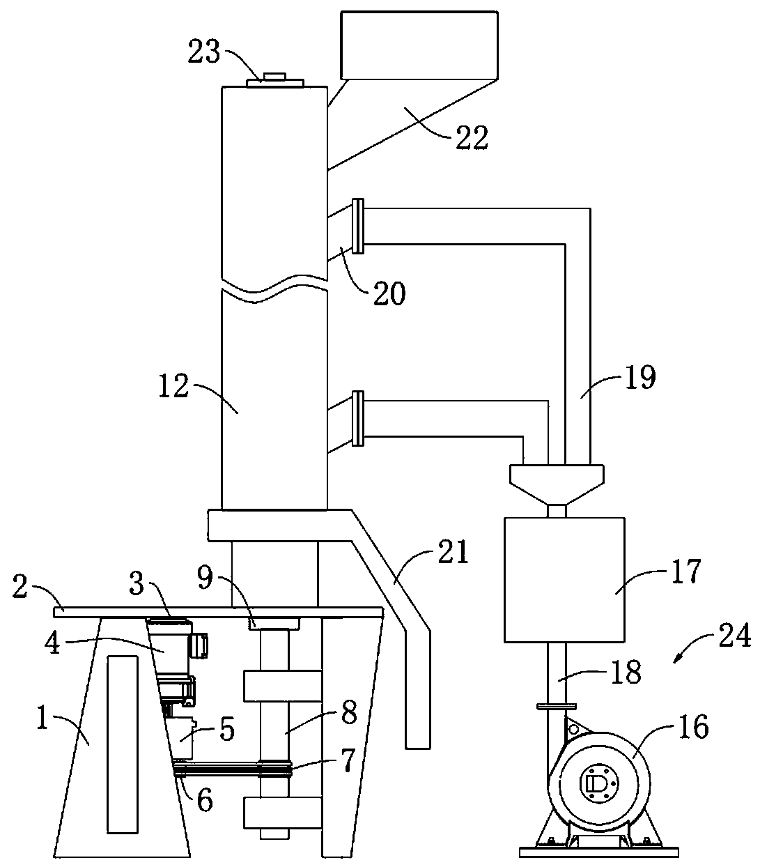
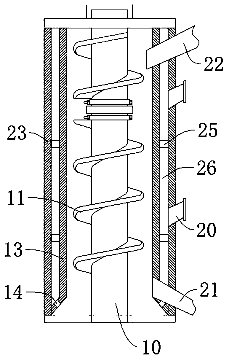
[0025] Please refer to the attached Figure 1-3 , an energy-saving and environment-friendly grain dryer, comprising a bracket 1, a support horizontal plate 2 is fixedly welded on the top of the support 1, and a motor base 3 is fixedly connected to the lower side of the support horizontal plate 2 through bolts, and the set support The horizontal plate 2 is convenient to install and fix the motor base 3, the motor 4 is fixedly installed under the motor base 3, the output end of the motor 4 is connected with a reducer 5, and the output end of the reducer 5 is connected with a belt Disk 6, the other side below the support horizontal plate 2 is fixedly installed with a shaft sleeve 9 through a vertical plate, and a drive shaft 8 is installed in the shaft sleeve 9. The drive shaft 8 and the belt pulley 6 are driven by a belt 7 connection, the top of the support horizontal plate 2 is fixedly welded with an outer cylinder 12, the inside of the outer cylinder 12 is provided with an inn...
PUM
| Property | Measurement | Unit |
|---|---|---|
| Aperture | aaaaa | aaaaa |
Abstract
Description
Claims
Application Information
PatSnap Eureka turns technology decisions into work you can execute. Powered by our Innovation Knowledge Graph, it runs expert workflows across engineering, life sciences, materials and intellectual property. Get your review-ready output in minutes.


