

Parallel time-space domain joint compression imaging method and device adopting DMD
A compressed imaging, space-time domain technology, applied in image communication, color TV parts, TV system parts, etc., can solve the problems of difficult image acquisition and high cost of imaging equipment
- Summary
- Abstract
- Description
- Claims
- Application Information
AI Technical Summary
Problems solved by technology
Method used
Image

Examples
Embodiment 1
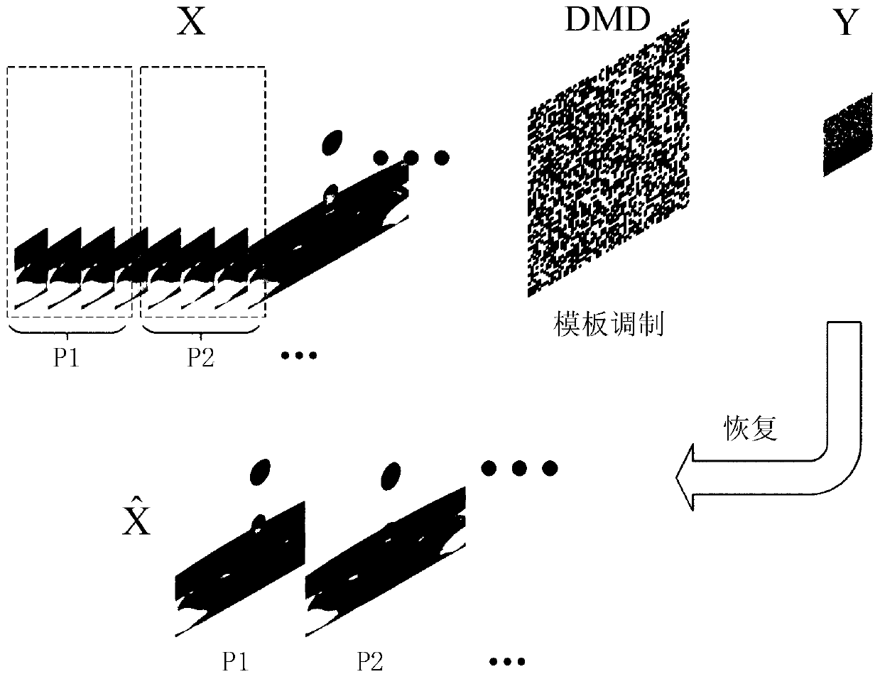
[0052] like figure 1 As shown, 8 frames of images with a resolution of 256×256, a pixel depth of 8 bits, and continuous slight changes are modulated using a spatiotemporal domain modulation template, and a frame of low-resolution images with a resolution of 64×64 is obtained after down-sampling. Finally, use the restoration algorithm to recover 2 frames of restored images with a resolution of 256×256 from the 64×64 low-resolution images, so as to achieve a 16-fold spatial resolution from the collected low-speed low-resolution images to the restored images (4 ×4), the time resolution is improved by 2 times.
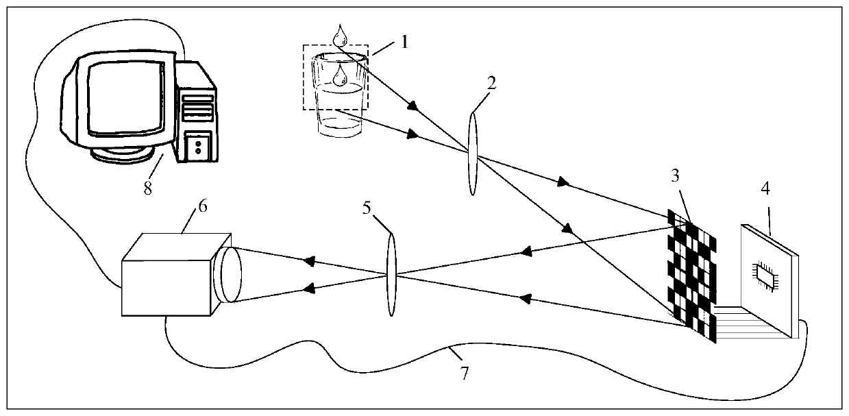
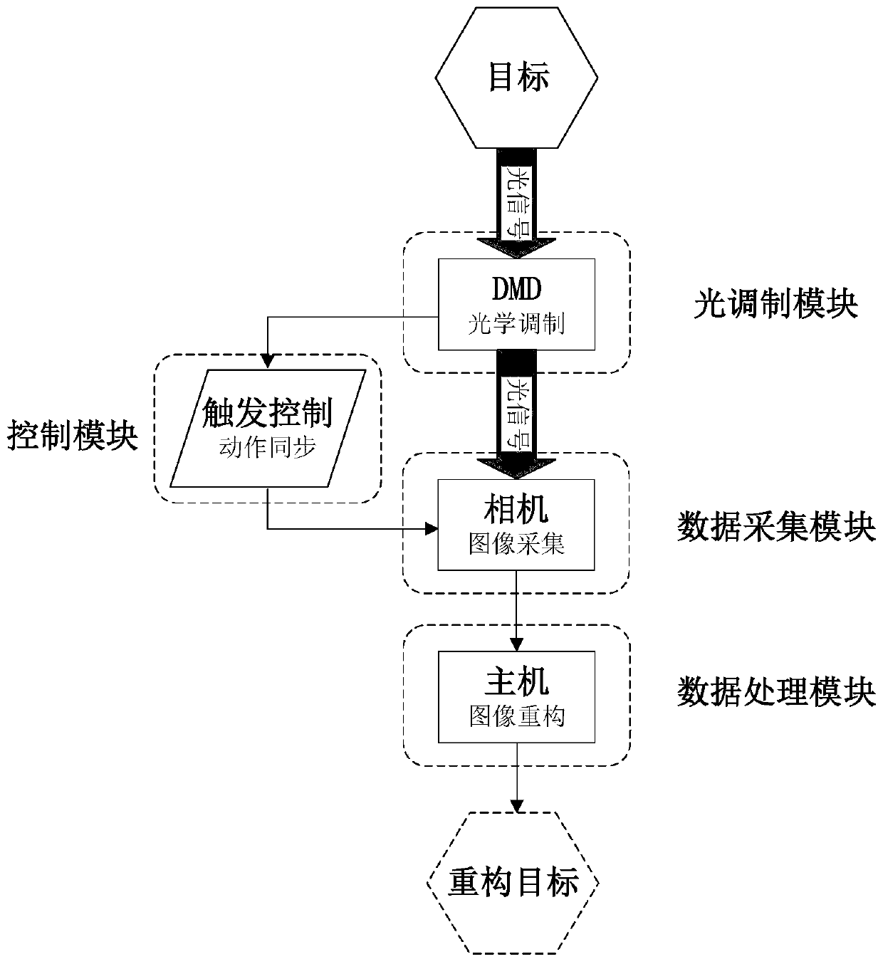
[0053] Step 1: The moving target or dynamic scene is imaged on the DMD through the optical system.
[0054] The object used in this embodiment is the original image X with 8 frames of continuous slight changes, the resolution is 256×256, and the pixel depth is 8 bits. Divide X into two groups, and record the first four frames as P 1 , and the group of the last four fram...
Embodiment 2
[0085] The operation step of embodiment 2 is the same as figure 1 As shown in , the difference is that the time domain compression ratio is improved and the shooting target is changed. The target resolution is changed to 128×128, the air domain compression ratio is 4:1, and the time domain compression ratio is 12:1, that is, k1=4, k2=12. Since k2 / k1=3, finally 3 frames of high-resolution images will be recovered from the modulated low-resolution images. which is figure 1 X should be 12 frames of images, divided into 3 groups, and finally recover 3 frames of high-resolution images ( figure 1 Add 4 frames of images after P2 in X as P3, Also add a frame P3). In addition, the control signals of DMD and camera should also change accordingly, such as Figure 4 As shown in b, DMD should contain 12 high levels, and the exposure time of the camera should be lengthened accordingly. All the other steps are the same as in Example 1. Figure 8 a is a low-speed low-resolution image ...
PUM
 Abstract
Description
Claims
Application Information