Switching power supply and X capacitor discharge circuit thereof

A technology of capacitor discharge circuit and switching power supply, which is applied in the direction of electrical components, output power conversion device, AC power input conversion to DC power output, etc. It can solve the problems of complex control circuit and time-consuming discharge detection process, and achieve circuit structure The effect of simplification and cost reduction

Active Publication Date: 2019-12-10
QISDA SUZHOU +1
View PDF5 Cites 3 Cited by
  • Summary
  • Abstract
  • Description
  • Claims
  • Application Information

AI Technical Summary

Problems solved by technology

[0007] The technical problem to be solved by the present invention is to solve the problem in the prior art that the ...

Method used


Image

  • Switching power supply and X capacitor discharge circuit thereof
  • Switching power supply and X capacitor discharge circuit thereof

Examples


Embodiment 1

[0041] In the first embodiment, taking the N-channel enhancement type MOS transistor as an example, the specific implementation of the application is described as follows:

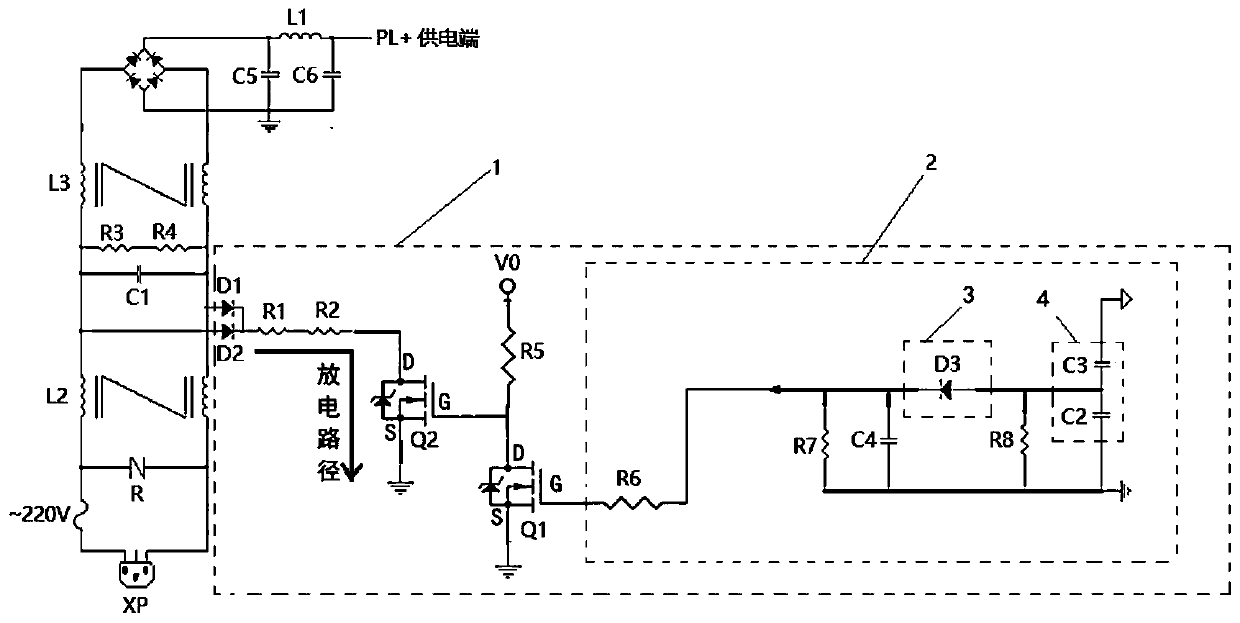
[0042] Such as figure 1 , the circuit in the dotted box 1 is the X capacitor discharge circuit, the circuit in the dotted box 2 is the drive circuit, the dotted box 3 is the rectifier circuit, and the dotted box 4 is the Y capacitor.

[0043] In this embodiment, both the first switch tube Q1 and the second switch tube Q2 are N-channel enhanced MOS tubes, and the N-channel enhanced MOS tubes are turned on when Ug>Us, that is, when the gate voltage is greater than the source voltage .

[0044] In this embodiment, both ends of the X capacitor are connected to the drain D of the second switching transistor Q2 via the first diode D1, the second diode D2 and the resistors R1 and R2 connected in series, wherein the first diode The anodes of the tube D1 and the second diode D2 are respectively connected to both ...

Embodiment 2

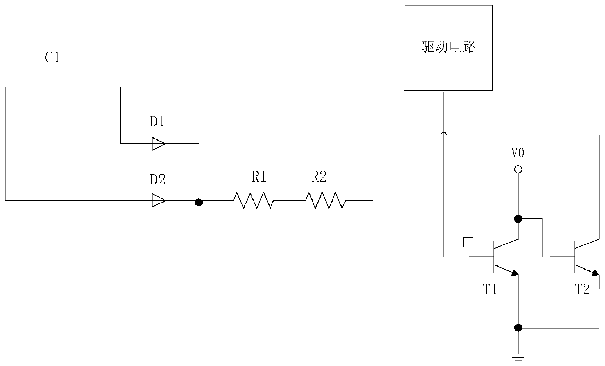
[0053] In the second embodiment, the first switch tube and the second switch tube are NPN transistors, the first switch tube can be configured as a first NPN transistor T1, and the second switch tube can be configured as a second NPN transistor T2. X capacitor discharge circuit 1 adopts as figure 2 circuit shown.

[0054] In this embodiment, the output end of the driving circuit 2 is connected to the base of the first NPN transistor T1, the emitter of the first NPN transistor T1 is grounded, and the collector of the first NPN transistor T1 is connected to the positive pole V0 of the power supply. The base of the second NPN transistor T2 is connected to the positive pole V0 of the power supply, the emitter of the second NPN transistor T2 is grounded, and the collector of the second NPN transistor T2 is connected to the X capacitor.

[0055] When the switching power supply is powered on, the drive circuit 2 is connected, and there will be a voltage output. The base of the firs...

Embodiment 3

[0057] On the basis of Embodiment 2, the driving circuit can adopt a single-chip microcomputer, and the single-chip microcomputer is powered by a transformer, and the signal output terminal of the single-chip microcomputer is connected to the base stage of the first NPN type transistor T1. When the transformer supplies power, the single-chip microcomputer outputs a high level, and the first NPN type The transistor T1 is turned on, and when the transformer is powered off, the single-chip microcomputer outputs a low level, and the first NPN transistor T1 is turned off.

[0058] In this embodiment, the specific discharge process of the C capacitor is the same as the above-mentioned embodiment 2 and embodiment 1, and will not be repeated here.


PUM


Abstract

The invention relates to a switching power supply and an X capacitor discharge circuit thereof. The discharge circuit comprises a power supply, a first switching tube, a second switching tube and a driving circuit, wherein both the first switching tube and the second switching tube are provided with a control port and two switching ports, the input end of the driving circuit is connected with thepower supply output end of the switching power supply, and the output end of the driving circuit is connected with the control port of the first switching tube; the control port of the second switching tube is connected with the positive electrode of the power supply, the first switching port serving as input of the second switching tube is connected with an X capacitor, and the second switch porting serving as output of the second switching tube is grounded; the first switching port serving as input of the first switching tube is connected with the positive electrode of the power supply, andthe second switching port serving as output of the first switching tube is grounded. The circuit structure is greatly simplified, so that the cost is further reduced, and the problem that the existingdischarge circuit is complex in structure is solved.

Description

technical field [0001] The present application relates to the field of switching power supplies, in particular to a switching power supply and an X capacitor discharge circuit thereof. Background technique [0002] In an AC / DC switching power supply, in order to solve the problem of electromagnetic interference, an EMI filter circuit is generally provided at the input end, and the EMI filter circuit generally includes an X capacitor connected in parallel between the live line and the neutral line at the input end of the AC power supply. When the AC power at the input end of the AC / DC switching power supply is disconnected, a certain voltage will remain on the X capacitor. If a person touches the input electrode of the switching power supply, the residual voltage on the X capacitor may cause electric shock to people. Therefore, it is stipulated in the safety standard that when the switching power supply is disconnected from the input power supply, the voltage on the X capacit...

Claims


Application Information

Patent Timeline
IPC IPC(8): H02M1/32H02M1/44H02M7/217
CPCH02M1/32H02M1/44H02M7/217H02M1/322
Inventor 阙锦盛陈衍坚徐圣尧周逸群
Owner QISDA SUZHOU
Why Eureka
Try Eureka