A vital sign monitoring device

A vital sign and monitoring device technology, applied in diagnostic recording/measurement, medical science, diagnosis, etc., can solve problems such as inability to accurately extract breathing and heartbeat signals, complex manufacturing process, complex demodulation method, etc., and achieve easy signal resolution Adjustment, high sensitivity, and the effect of avoiding accidents

Active Publication Date: 2022-03-08
武汉凯锐普医疗科技有限公司
View PDF15 Cites 1 Cited by
  • Summary
  • Abstract
  • Description
  • Claims
  • Application Information

AI Technical Summary

Problems solved by technology

The sensing system based on the principle of optical fiber sensing has the characteristics of high sensitivity, good comfort, and anti-electromagnetic interference. However, the current monitoring device system structure and manufacturing process based on fiber grating sensors are complicated, and the acquired signals need to be demodulated by wavelength, which leads to system failure. The cost is too high and the demodulation method is complicated
The monitoring system based on the principle of interference either requires phase demodulation, which leads to complex demodulation methods and high system costs, or the interference signal is easily affected by the environment, polarization and phase fading and cannot accurately extract the complete breathing and heartbeat signals.

Method used


Image

  • A vital sign monitoring device
  • A vital sign monitoring device
  • A vital sign monitoring device

Examples


Embodiment 1

[0050] The vital sign monitoring device of this embodiment includes a laser light source 1 , a pressure sensitive device 2 , a photoelectric conversion module 3 , a vital sign signal extraction and analysis module 4 , a Bluetooth communication module 5 and an intelligent terminal 6 . Wherein, the laser light source 1, the photoelectric conversion module 3, the vital sign signal extraction and analysis module 4, the bluetooth communication module 5 and the intelligent terminal 6 adopt the existing technology, the difference lies in the setting of the pressure sensitive device 2.

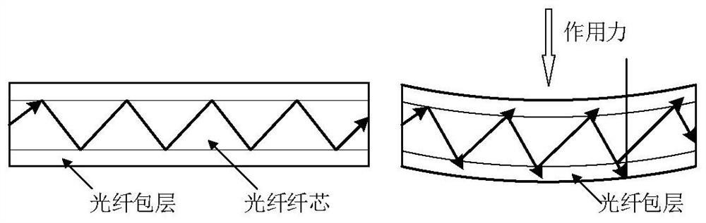
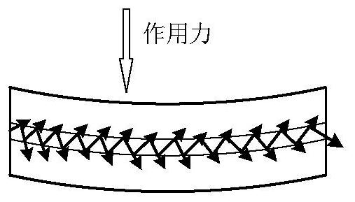
[0051] The pressure-sensitive device 2 of this embodiment includes a sensing optical fiber 21 and a thin film 22, wherein the sensing optical fiber 21 has a diameter of 9 μm, and the sensing optical fiber 21 is arranged on the surface of the thin film 22 and runs in an "S" shape or a spiral shape. Wire.

Embodiment 2

[0053] The vital sign monitoring device of this embodiment is basically the same as that of Embodiment 1, except that the diameter of the sensing fiber 21 is 5 μm.

Embodiment 3

[0055] The vital sign monitoring device of this embodiment is basically the same as that of Embodiment 2, the difference is that the sensing optical fiber 21 includes two sections of "S" shaped wires, which are arranged opposite to each other up and down, and the hard wire 23 is provided with two One of the hard wires 23 is 2.5cm away from the top of the "S"-shaped wiring on the upper side, and the diameter of the hard wire 23 is 1mm; the other hard wire 23 is 2.5cm away from the bottom end of the "S"-shaped wiring on the lower side. The hard wire 23 has a diameter of 0.4mm.

[0056] The pressure-sensitive device 2 of Examples 1-3 is placed flat in the mattress, and the same tester is used to lie flat on the mattress area where the pressure-sensitive device 2 is located, and the breathing rate and heartbeat are monitored through the vital sign signal extraction and analysis module 4 rate, get as Figure 5 The results shown.

[0057] Depend on Figure 5 It can be seen that t...


PUM


Abstract

The invention proposes a vital sign monitoring device, which monitors vital sign information based on the principle of bending loss, which can reduce the influence of optical phase fading and polarization, and monitor vital signs such as breathing and heartbeat signals more accurately; by setting a small core diameter optical fiber , the small vibration caused by extrusion caused by breathing and heartbeat causes the bending change of the optical fiber, and the optical signal will undergo obvious intensity modulation in the small core fiber with more sensitive bending loss, and the output at the output end of the sensing fiber follows the breathing and heartbeat The optical power of the correlation change has higher sensitivity and better accuracy; setting a hard line can have a sensitization effect.

Description

technical field [0001] The invention relates to the field of monitoring human vital signs, in particular to a vital sign monitoring device. Background technique [0002] With the development of social economy and technology and the improvement of people's requirements for quality of life, people's demand for testing their own health is increasing. Respiratory rate and heart rate are the most basic vital signs of the human body. Morbid signs of the human body are often reflected in abnormal respiration rate and heart rate. Therefore, daily real-time monitoring of respiration rate and heart rate is of great significance for human health assessment and disease prevention . Long-term breathing rate and heartbeat monitoring can enable the health status of the monitored person to be monitored and mastered in real time. However, most traditional monitoring systems use contact-type wearable devices, which have poor user experience. The monitoring not only interferes with the life o...

Claims


Application Information

Patent Timeline
Patent Type & Authority Patents(China)
IPC IPC(8): A61B5/0205A61B5/00
CPCA61B5/0059A61B5/0205A61B5/02416A61B5/02427A61B5/0816
Inventor 李政颖黄国良赵涛
Owner 武汉凯锐普医疗科技有限公司
Why Eureka
Try Eureka