An orthopedic nail removal device

A technology of orthopedics and nail discs, applied in the field of orthopedic surgery equipment, can solve the problems of increased trauma, difficulty, and easy secondary fractures, and achieve the effects of avoiding secondary injuries, simplifying the nail removal process, and preventing bone nails from slipping

Active Publication Date: 2022-07-05
蔺超
View PDF5 Cites 0 Cited by
  • Summary
  • Abstract
  • Description
  • Claims
  • Application Information

AI Technical Summary

Problems solved by technology

[0003] At present, in fracture surgery, the use of bone nails and steel plates to fix the fracture site is a commonly used surgical method in existing operations. The bone nails need to be removed after being implanted in the human body for a period of time. The body will be connected to the human bone, which adds a lot of difficulty to the doctor when taking it out, and the common surgical nail removal method is to clamp the metal exposed part with forceps and rotate it strongly, which can easily damage the nail groove and the direction of the human body and the bone nail. Adjacent tissue, or the fracture site is damaged again, is also easy to break the bone screw, which increases the difficulty of taking out the bone screw and brings secondary injury to the patient; Screw head slippage makes it difficult to take out the nail; or use a drill to break the nut first to take out the steel plate and then slot around the screw to drill holes to take out the screw. This operation process increases the trauma, re-trauma at the fracture site, and is very prone to secondary fractures

Method used


Image

  • An orthopedic nail removal device
  • An orthopedic nail removal device
  • An orthopedic nail removal device

Examples


Embodiment Construction

[0023] The present invention will be further described below in conjunction with specific embodiments. Among them, the accompanying drawings are only used for exemplary description, and they are only schematic diagrams, not physical drawings, and should not be construed as restrictions on this patent; in order to better illustrate the embodiments of the present invention, some parts of the accompanying drawings will be omitted, The enlargement or reduction does not represent the size of the actual product; it is understandable to those skilled in the art that some well-known structures and their descriptions in the accompanying drawings may be omitted.

[0024] The same or similar numbers in the drawings of the embodiments of the present invention correspond to the same or similar components; in the description of the present invention, it should be understood that if there are terms “upper”, “lower”, “left” and “right” The orientation or positional relationship indicated by e...


PUM


Abstract

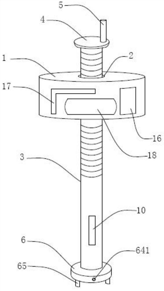
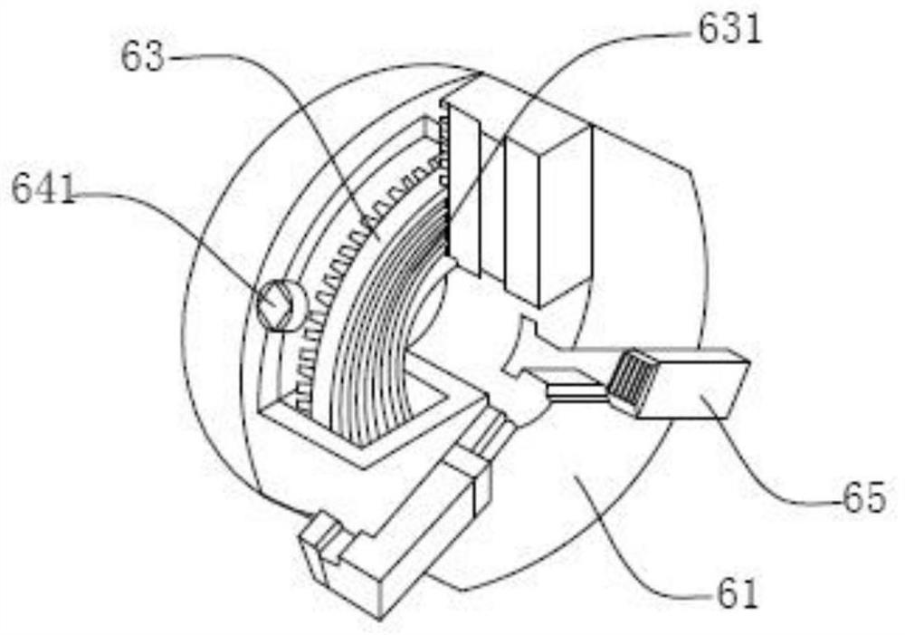
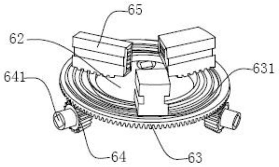
The invention belongs to the technical field of orthopaedic surgery equipment, and in particular relates to an orthopaedic nail removal device, comprising a fixing plate, a guide rod is threadedly connected to the middle of the fixing plate, the top of the guide rod is provided with a rotating handle, and the The bottom end is provided with a nail taking plate and a rocker, the nail taking plate is provided with a large bevel gear, one side of the large bevel gear is meshed with 3 small bevel gears, and the other side of the large bevel gear is provided with a plane thread , the plane thread is provided with three clamping blocks, and the rocker shown extends into the square groove of the bevel pinion. The orthopaedic nail removal device provided by the invention has simple structure and reasonable design, can firmly clamp the bone nail, prevent the bone nail from slipping, simplifies and quickens the nail removal process, and can easily remove the bone nail even if the bone nail is broken In the present invention, the bone nail is pulled out manually and slowly, which can avoid the secondary damage to the bone caused by the vibration generated when the electric nail is pulled out.

Description

technical field [0001] The invention belongs to the technical field of orthopedic surgery equipment, and in particular relates to an orthopedic nail removal device. Background technique [0002] In clinical medicine, fracture is one of the common diseases of bone trauma. The most commonly used method to treat fractures is to implement internal fixation surgery, that is, after the fracture site is reduced, the reduced bone is fixed with the help of bone plates and bone nails made of metal materials. connected, the screws need to be removed during the process of removing the bone plate after internal fixation surgery. [0003] At present, in the fracture operation, the use of bone nails and steel plates to fix the fracture site is a common surgical method in existing operations. The bone nails need to be removed after being implanted in the human body for a period of time. The body will be connected with the human bones, which brings great difficulties to the doctor when taki...

Claims


Application Information

Patent Timeline
Patent Type & Authority Patents(China)
IPC IPC(8): A61B17/92
CPCA61B17/92
Inventor 蔺超王雅宁张国强刘增艳
Owner 蔺超
Why Eureka
Try Eureka