

High-precision quick reaction mechanical hand
A fast-response, manipulator technology, applied in the field of manipulators, can solve the problems of low flexibility, large workload, time-consuming and labor-intensive, etc., and achieve the effect of saving labor costs, flexible use, and reducing use costs.
- Summary
- Abstract
- Description
- Claims
- Application Information
AI Technical Summary
Problems solved by technology
Method used
Image

Examples
Embodiment 1
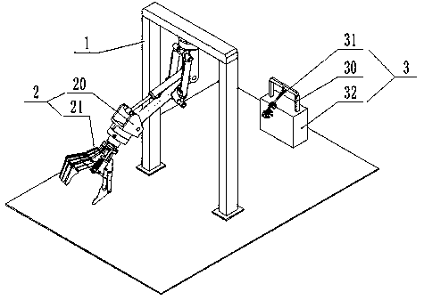
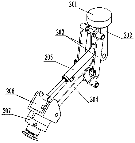
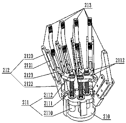
[0026] Such as Figure 1-5As shown, a high-precision quick-response manipulator provided in this embodiment includes a first gantry 1 and a manipulator body 2, and the manipulator body 2 includes a manipulator 20 and a palm 21 connected to the manipulator 20. Said mechanical arm 20 drives said palm 21 to perform rotational movement and swing movement; said palm 21 comprises a link mechanism 212, a linear drive mechanism 211, a connecting seat 210 and a plurality of clamping fingers 213; said connecting seat 210 is connected to said The mechanical arm 20 is connected; a plurality of clamping fingers 213 are respectively connected to the linear drive mechanism 211 through a link mechanism 212; the linear drive mechanism 211 is connected to the connecting seat 210; the linear drive mechanism 211 drives The movement of the link mechanism 212 drives the clamping fingers 213 to open or close.
[0027] In this embodiment, if image 3 As shown, the linear drive mechanism 211 include...
Embodiment 2
[0037] Such as Figure 1-5 As shown, Embodiment 2 is based on Embodiment 1. The high-precision quick-response manipulator also includes a manipulator teaching mechanism 3, and the manipulator teaching mechanism 3 includes a second gantry 30, a wearable manipulator 31 and a control system 32. The wearable manipulator 31 includes a rotary table 310, an arm frame 312, a fixed frame 317 on the back of the hand, a plurality of finger covers 319 and sensors; the sensors include angle sensors and linear displacement sensors, and the angle sensors include the first angle sensor 311 and The second angle sensor 316, the linear displacement sensor includes a first linear displacement sensor 313, a second linear displacement sensor 320 and a third linear displacement sensor 318; the second gantry 30 is installed on the control system 32; The turntable 310 is rotatably connected with the second gantry 30; one end of the arm frame 312 is rotatably connected with the turntable 310, and the o...
PUM
 Abstract
Description
Claims
Application Information