Heavy oil storing tank VOCs safe recycling system and process

A recovery system and heavy oil technology, applied in containers, large containers, gas treatment, etc., can solve the problems of high dependence on pressure sensors, storage tanks beyond the pressure range, and large nitrogen consumption, so as to save nitrogen consumption and excellent treatment effect , increase the effect of investment

Active Publication Date: 2019-12-13
CHINA PETROLEUM & CHEM CORP +1
7 Cites 0 Cited by

AI-Extracted Technical Summary

Problems solved by technology

[0004] However, the above-mentioned prior art consumes a lot of nitrogen and relies heavily on the pressure se...

Method used

The present invention enters device heating furnace blower inlet or burner to incinerate at suction blower outlet, does not increase any cost, and is safe and reliable; Heavy oil volatile gas mostly is C5~C10 component and contains certain water vapor, It is in a gaseous state at room temperature. In order to prevent the maximum recovery of heavy oil, an oil recovery device is installed in the pipeline between the exhaust device and the ex...

Abstract

The invention discloses a heavy oil storing tank VOCs safe recycling system and process and belongs to the technical field of petrochemical engineering environment protecting. The heavy oil storing tank VOCs safe recycling system comprises a first heavy oil storing tank, a second heavy oil storing tank, a first gas sucking cooling liquid window, a second gas sucking cooling liquid window and a gassucking draught fan; an exhausting port of the first heavy oil storing tank is connected with the gas sucking draught fan through a first pipeline; the middle portion of the first pipeline is connected with a second pipeline which is used for conveying heavy oil products after being cooled into an underground oil dirt tank; the gas sucking draught fan is further connected with a heating furnace burning nozzle; heavy oil volatile gas sucked out through the gas sucking draught fan is introduced into the heating furnace burning nozzle to be incinerated; and the first pipeline and a third pipeline are provided with breather valves and gas sucking port silencers correspondingly. Due to the heavy oil storing tank VOCs safe recycling system and process, the pollution to the environment by oil and gas volatizing can be prevented, the safety and the reliability of the recycling process are guaranteed, nitrogen is hardly consumed during normal operation, and noise pollution cannot be caused, either.

Application Domain

Gas treatmentDispersed particle separation +1

Technology Topic

Noise pollutionPetrochemical +10

Image

  • Heavy oil storing tank VOCs safe recycling system and process

Examples

  • Experimental program(1)

Example Embodiment

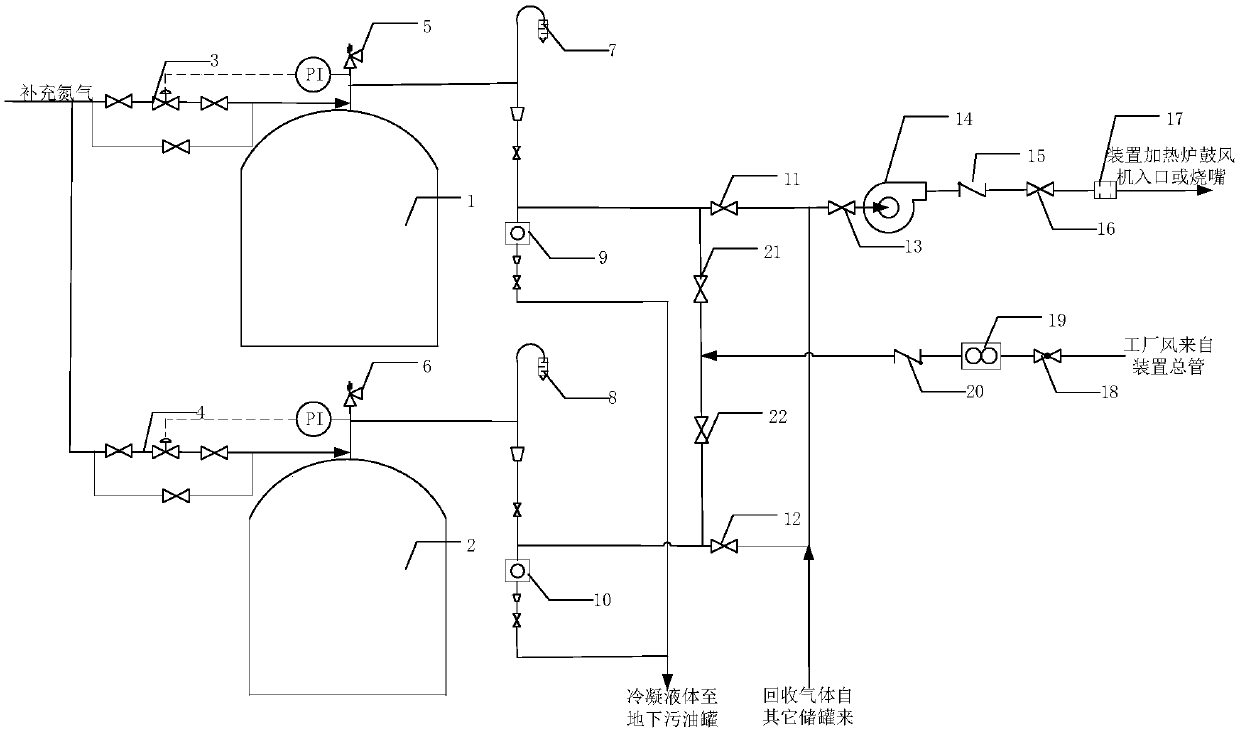
[0030] The present invention proposes a VOCs safe recovery system and recovery process for heavy oil storage tanks. In order to make the advantages and technical solutions of the present invention clearer and clearer, the present invention will be described in detail below with reference to specific embodiments.
[0031] Such as figure 1 As shown, a VOCs safety recovery system for heavy oil storage tanks of the present invention includes heavy oil storage tank-1, heavy oil storage tank-2, suction cooling liquid window 9 and suction cooling liquid window 10, The suction fan 14 and the process pipeline and pipe fittings. The process pipeline includes a first pipeline, a second pipeline, a third pipeline, and a fourth pipeline. The exhaust port of the heavy oil storage tank 1 is connected to the suction through the first pipeline. The other end of the suction fan is connected to the burner of the heating furnace. The heavy oil volatile gas drawn by the suction fan is passed into the burner of the heating furnace for incineration. The second pipe is connected in the middle of the first pipe, and the second The pipeline is used to send the cooled heavy oil to the underground oil tank. The first pipeline is provided with a first suction inlet valve 11, a suction fan inlet master valve 13, and a suction fan 14 and a heating furnace burner. The outlet check valve 15 of the suction fan and the outlet master valve of the suction fan 16 are arranged in sequence between the outlet check valves and the outlet master valve of the suction fan. Process pipes such as the outlet check valve and the outlet master valve of the suction fan are provided for the convenience of operation. The breathing valve 5, the first suction port muffler 7, the first breathing valve is close to the exhaust port of the heavy oil storage tank 1, and the second pipe is provided with the suction cooling liquid window 1.
[0032] The exhaust port of the heavy oil storage tank 2 is connected to the suction fan 14 through a third pipe, and a fourth pipe is connected to the middle of the third pipe. The fourth pipe is used to send the cooled heavy oil to In the underground oil tank; the second breathing valve 6, the second suction port muffler 8, and the second suction inlet valve 12 are provided on the third pipeline. Among them, the second breathing valve is close to the heavy oil storage tank 2 The exhaust port, the fourth pipe is provided with the second suction cooling liquid window.
[0033] In the above scheme, because the suction fan is directly connected to the atmosphere, and its size is specially designed to ensure the pressure ≮-0.2KPa, it will not cause the heavy oil storage tank to collapse, and a small amount of air entering the gas phase space of the storage tank will The mixed gas of oil and gas will be higher than the upper limit of the explosion limit range, and there is no risk of explosion; because the first suction port muffler 7 and the second suction port muffler 8 are set, the aerodynamic noise can be guaranteed to be ≯60db, so it will not Cause noise pollution.
[0034] In order to prevent safety accidents caused by tempering, the present invention preferably has a flame arrestor 17 between the suction fan and the burner of the heating furnace.
[0035] In order to ensure that the pipeline can be unblocked and purged in time when the pipeline is blocked, the present invention preferably uses a factory air purging device. The factory air purging device is connected to the first pipe, the second pipe, the third pipe, and the fourth pipe. The air purging device is respectively connected to the intersection of the first pipeline, the second pipeline and the intersection of the third and fourth pipelines through the main pipeline. The main pipeline is provided with a factory air master valve 18, a factory wind rotor flowmeter 19, and a factory. The air check valve 20 is provided with a first suction inlet purge valve 21 between the main pipe and the first pipe and the second pipe, and between the main pipe and the third pipe and the fourth pipe. The second suction inlet purge valve 22.
[0036] Furthermore, during normal operation, neither the heavy oil storage tank 1 nor the heavy oil storage tank 2 needs to be supplemented with nitrogen or other media, which achieves the purpose of saving nitrogen consumption. In the present invention, it is preferable that both the heavy oil storage tank 1 and the heavy oil storage tank 2 are connected with a nitrogen supply device, and when the temperature drops suddenly (such as strong wind, rainy weather), the storage tank is filled with oil, etc., the pressure sensor senses the storage tank Pressure changes, that is: when the pressure in heavy oil storage tank one and heavy oil storage tank two is lower than -0.2KPa, the nitrogen sealing valve group one and the nitrogen sealing valve group two and four are automatically opened to replenish nitrogen to the storage tank; if When the pressure continues to drop to -0.295KPa, the breathing valve of the storage tank will automatically open to fill the tank with air to keep the pressure of the storage tank stable.
[0037] The present invention will be further described below in conjunction with specific recycling processes.
[0038] The specific recycling process includes:
[0039] a. Turn on the suction fan. When the suction fan inhales through a suction port that is directly connected to the atmosphere, the first and third pipes connected to them are in a slight negative pressure state. At the same time, the heavy oil storage tank , The pressure in the second heavy oil storage tank is also slightly negative;
[0040] b With the operation of the suction fan, the gas in the heavy oil storage tank 1 and the heavy oil storage tank 2 are pumped out through the first pipe and the third pipe respectively. Among them, the oily mixed gas, the air entering the system, and the air through the suction The air entering from the port enters the suction fan together; the cooled heavy oil enters the underground sewage oil tank through the second pipe and the fourth pipe respectively;
[0041] c Send the remaining volatile oil and gas and air mixed gas from the outlet of the suction fan into the burner of the heating furnace for incineration.
[0042] When the suction fan pumps air through a device directly connected to the atmosphere, the outlet pipe of the breathing valve of the heavy oil storage tank connected with it is in a slightly negative pressure state (-0.2~-0.1KPa), and the heavy oil storage tank The pressure is equal. Therefore, the pressure in the storage tank is also slightly negative. Volatile oil and gas will enter the lower pressure fan inlet and will not enter the atmosphere disorderly, causing environmental pollution.
[0043] The invention does not increase any cost and is safe and reliable when the outlet of the suction fan enters the inlet of the blower or burner of the heating furnace of the device for incineration; the volatile gas of heavy oil is mostly C5-C10 components and contains a certain amount of water vapor. In gaseous state, in order to prevent the recovery of heavy oil to the greatest extent, an oil recovery device is installed in the pipeline between the air extraction device and the air extraction fan. The cooled heavy oil is discharged to the underground sewage oil tank through the window and drain valve designed at the bottom of the pipeline to realize centralized recovery. During normal operation, the storage tank does not need to be supplemented with nitrogen and other media, thus achieving the purpose of saving nitrogen consumption. The factory air purging device is installed to ensure that the pipeline is blocked and used for purge.
[0044] The parts not mentioned in the present invention can be realized by adopting or learning from existing technologies.
[0045] Although the terms such as suction fan, heavy oil storage tank one, heavy oil storage tank two, and first suction port muffler are used more in this article, the possibility of using other terms is not excluded. These terms are used only to describe and explain the essence of the present invention more conveniently; to interpret them as any additional limitation is contrary to the spirit of the present invention.
[0046] It should be further explained that the specific embodiments described in this document are merely illustrative of the spirit of the present invention. Those skilled in the art to which the present invention pertains can make various modifications or additions to the specific embodiments described or use similar alternatives, but they will not deviate from the spirit of the present invention or exceed the definition of the appended claims. Range.

PUM

no PUM

Description & Claims & Application Information

We can also present the details of the Description, Claims and Application information to help users get a comprehensive understanding of the technical details of the patent, such as background art, summary of invention, brief description of drawings, description of embodiments, and other original content. On the other hand, users can also determine the specific scope of protection of the technology through the list of claims; as well as understand the changes in the life cycle of the technology with the presentation of the patent timeline. Login to view more.

Similar technology patents

Thermal regeneration method of silicate inorganic coating wet state waste sand

ActiveCN108723287AGood processing effect
Owner:CHONGQING CHANGJIANG RIVER MOLDING MATERIAL GRP

Classification and recommendation of technical efficacy words

  • big investment
  • Good processing effect

Technique for biological treatment of mine acidic wastewater

InactiveCN101219844AReduce waste water treatment costsGood processing effect
Owner:TAIYUAN UNIV OF TECH

Paracoccus sp. and culture application thereof

ActiveCN106635858AStrong salt toleranceGood processing effect
Owner:CHINA PETROLEUM & CHEM CORP +1
Why Eureka
Try Eureka