

Method for manufacturing liquid crystal display device
- Summary
- Abstract
- Description
- Claims
- Application Information
AI Technical Summary
Benefits of technology
Problems solved by technology
Method used
Image

Examples
embodiment mode 1
[0070] A method for manufacturing a channel protection type thin film transistor is described in this embodiment mode.
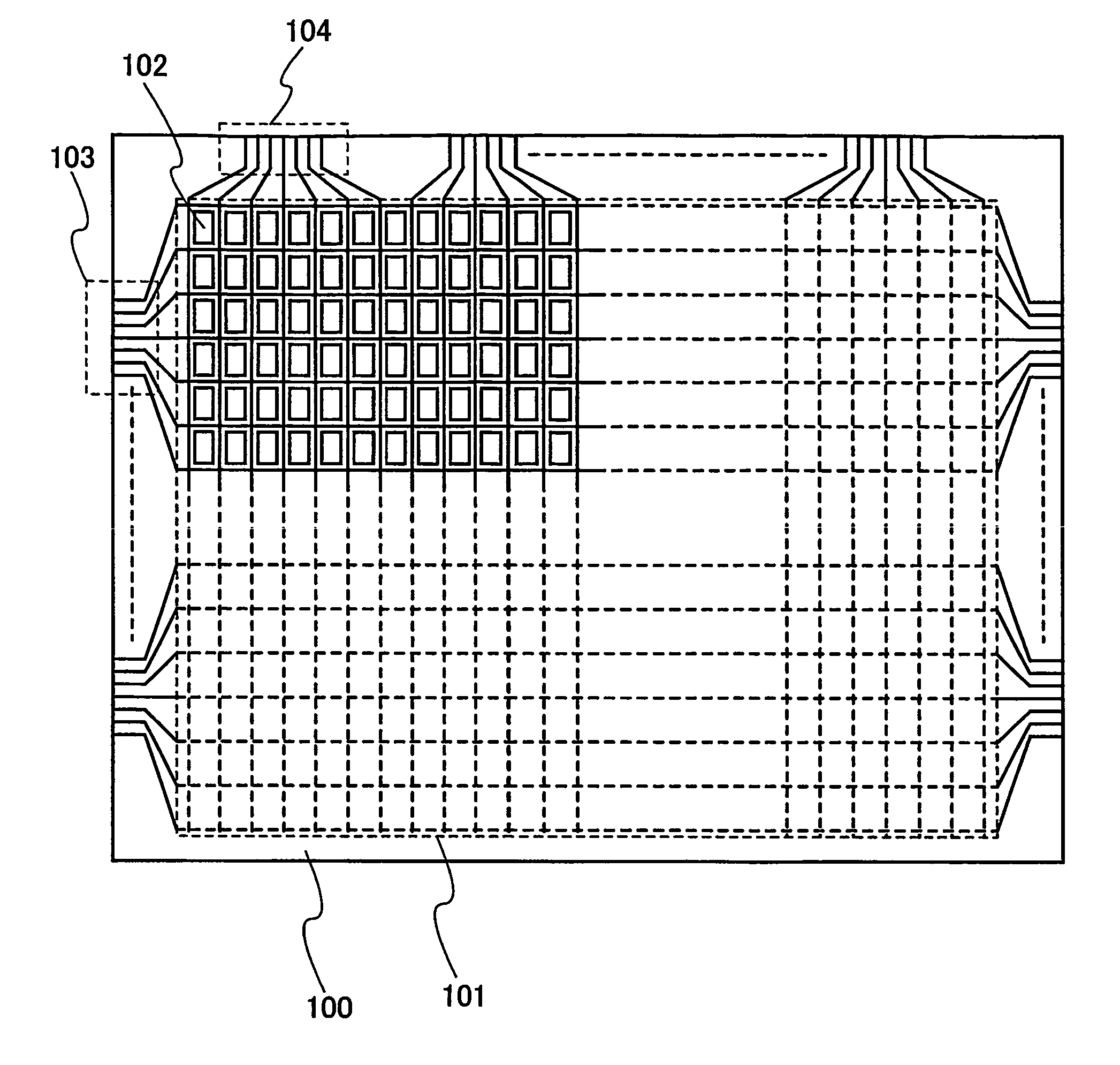
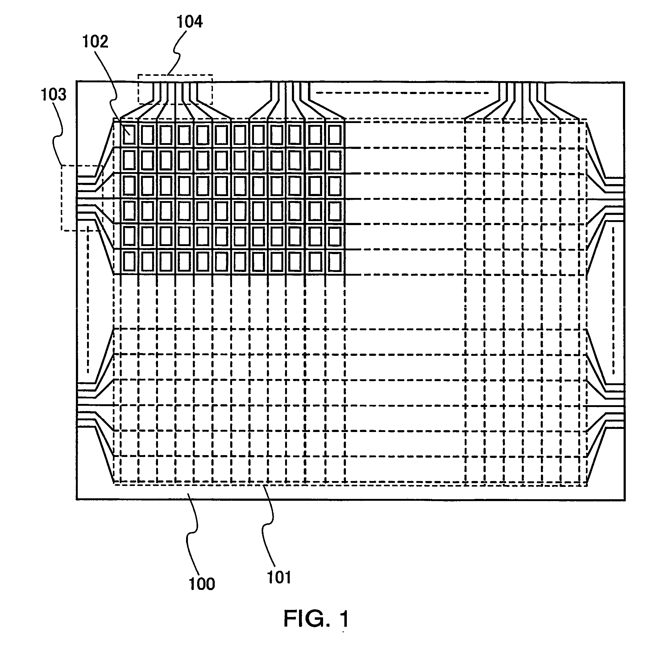
[0071]FIG. 4B shows a step of forming a gate electrode layer and a gate wiring layer which is connected to the gate electrode layer over a substrate 100 by a droplet discharge method. Note that FIG. 4B schematically shows a longitudinal sectional structure, and a planar structure corresponding to a line A-B and a line C-D in FIG. 4B is shown in FIG. 13, which can also be referred to simultaneously.
[0072] In addition to a non-alkaline glass substrate manufactured by a fusion method or a floating method such as barium borosilicate glass, alumino borosilicate glass, or aluminosilicate glass and a ceramic substrate, a plastic substrate having enough heat resistance to withstand a processing temperature of this manufacturing step or the like can be used for the substrate 100. In addition, a semiconductor substrate of single crystal silicon or the like, or a metal substr...
embodiment mode 2
[0112] Embodiment Mode 1 shows a structure in which the pixel electrode layer 224 and the source-drain wiring layer 220 are directly in contact with each other; however, an insulating layer may be interposed therebetween as another mode.
[0113] In this case, an insulating layer 240 functioning as a protective film is formed when up to the step show in FIG. 5C is completed (ref. FIG. 8A). A coating of silicon nitride or silicon oxide formed by a sputtering method or a plasma CVD method may be employed as the protective film. It becomes necessary to form an opening 241 in the insulating layer 240, and the source-drain wiring layer 220 is electrically connected to a pixel electrode layer 224 through the opening 241 (ref. FIG. 8B). At the time of forming the opening 241, an opening 242 necessary for attaching a connection terminal later may be simultaneously formed. Reference number 244 denotes an insulating layer.
[0114] A method for forming the openings 241 and 242 is not specifically ...
embodiment mode 3
[0116] A method for manufacturing a channel etch thin film transistor is described in this embodiment mode.
[0117] A gate wiring layer 202, a gate electrode layer 203, and a capacitor wiring layer 204 are formed over a substrate 100 by discharging a composition including a conductive material with a droplet discharge method. Subsequently, a gate insulating layer is formed to be a single layer or to have a laminated structure by a plasma CVD method or a sputtering method. A specifically preferable mode of the gate insulating layer corresponds to a lamination body of three layers of an insulating layer 208 made of silicon nitride, an insulating layer 209 made of silicon oxide, and an insulating layer 210 made of silicon nitride. Furthermore, up to a semiconductor layer 211 functioning as an active layer is formed. The above-mentioned steps are similar to those in Embodiment Mode 1.
[0118] An n-type semiconductor layer 301 is formed on the semiconductor layer 211 (ref. FIG. 10A). Next,...
PUM
 Abstract
Description
Claims
Application Information