
Soft switch direct current converter based on coupling inductor

A technology of DC converters and coupled inductors, which is applied in the direction of converting DC power input to DC power output, adjusting electrical variables, and high-efficiency power electronics conversion. It can solve the problems of large voltage and current stress, unsatisfactory effects, complex topology and control logic. and other problems, to achieve the effect of strong load adaptability and high reliability

Pending Publication Date: 2019-12-13
WUXI WEIFU HIGH TECH CO LTD
View PDF0 Cites 1 Cited by
  • Summary
  • Abstract
  • Description
  • Claims
  • Application Information

AI Technical Summary

Problems solved by technology

The soft switching structure proposed in recent years has solved the above contradictions to a certain extent, but the effect is not ideal.
Some converters introduce auxiliary switches to achieve soft turn-on or soft turn-off, but there are problems such as inability to fully realize soft switching, large voltage and current stress, complex topology and control logic, etc.

Method used


Image

  • Soft switch direct current converter based on coupling inductor
  • Soft switch direct current converter based on coupling inductor

Examples


Embodiment Construction

[0018] The present invention will be further described below in conjunction with specific drawings and embodiments.

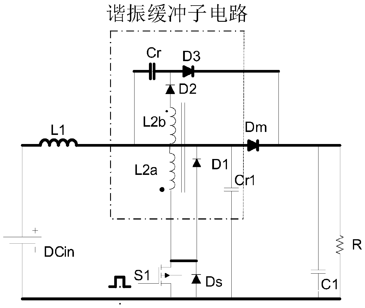
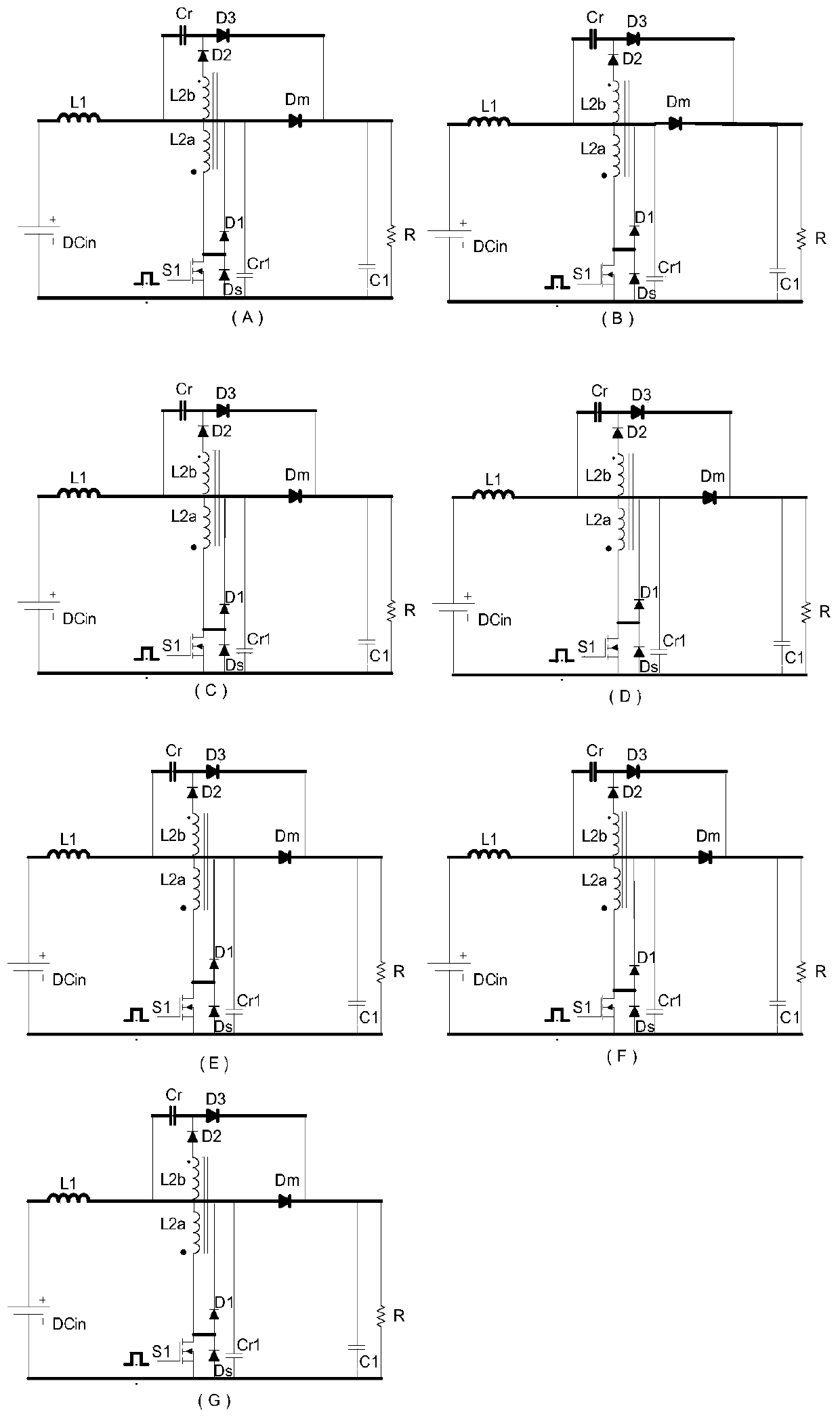
[0019] like figure 1 As shown, a soft-switching DC converter based on coupled inductors proposed by the present invention is a soft-switching boost converter, including a main circuit and a resonant buffer sub-circuit;

[0020] The main circuit includes inductor L1, switch S1, diodes Ds, Dm, capacitor C1;

[0021] The resonant snubber sub-circuit includes coupled inductors L2a, L2b, capacitors Cr, Cr1, diodes D1, D2, D3; used to realize the boost converter working in a soft switching state;

[0022] One end of the inductor L1 is used to connect the positive pole of the power supply DCin, and the other end is connected to one end of the capacitor Cr, the opposite ends of the inductors L2a and L2b, the cathode of the diode D1, one end of the capacitor Cr1 and the anode of the diode Dm; the end of the inductor L2b is connected to the anode of the diode D2, The c...


PUM


Abstract

The invention provides a soft switch direct current converter based on a coupling inductor. The converter comprises a main circuit and a resonance buffer sub-circuit. One end of an inductor L1 is connected to an anode of a power supply DCin, and the other end is connected with one end of a capacitor Cr, synonym ends of inductors L2a and L2b, a cathode of a diode D1, one end of a capacitor Cr1 andthe anode of a diode Dm. A dotted end of an inductor L2b is connected with the anode of a diode D2, and a cathode of the diode D2 is connected with the other end of the capacitor Cr and the anode of adiode D3. A cathode of the diode D3 is connected with the cathode of a diode Dm, one end of the capacitor C1 and one end of the load R. A dotted end of an inductor L2a is connected with one end of aswitch S1, the anode of a diode D1 and the cathode of a diode Ds. The other end of the switch S1 is connected with the anode of the diode Ds, the other end of the capacitor Cr1, the other end of the capacitor C1, the other end of the load R and the cathode of the power supply DCin. A control end of the switch S1 is connected with a control signal. In the invention, on-off losses and current and voltage impacts of the switch are significantly reduced.

Description

technical field [0001] The invention relates to a DC converter circuit suitable for switching power supplies, in particular to a soft-switching DC converter based on coupled inductance. Background technique [0002] At present, Boost converters regulated by PWM (pulse width modulation) are widely used in various industrial fields such as aerospace, automobiles and ships. As the switching frequency of this type of converter is continuously increased due to its weight reduction, the efficiency gradually decreases. The electromagnetic noise is also more obvious at the moment of switch transition. Soft switching technology can well solve the above two problems. The soft switching structure proposed in recent years has solved the above contradiction to a certain extent, but the effect is not ideal. Some converters introduce auxiliary switches to achieve soft turn-on or soft turn-off, but there are problems such as inability to fully realize soft switching, large voltage and cu...

Claims


Application Information

Patent Timeline
IPC IPC(8): H02M3/155
CPCH02M3/155H02M1/0058Y02B70/10
Inventor 钱伟张琪马腾飞陈方圆
Owner WUXI WEIFU HIGH TECH CO LTD
Learn More