Camera lens machining method

A lens processing and camera technology, which is applied to metal processing equipment, lenses, manufacturing tools, etc., can solve the problems of low hole yield rate and large error of camera lens shape, so as to improve the stability of installation, reduce workload, and align accurate effect

Active Publication Date: 2019-12-17
LENS TECH CHANGSHA
View PDF12 Cites 0 Cited by
  • Summary
  • Abstract
  • Description
  • Claims
  • Application Information

AI Technical Summary

Problems solved by technology

[0004] The purpose of the present invention is to provide a camera lens processing method to solve the technical problems in the prior art that the shape error is relatively large and the hole yield rate is low when processing the camera lens

Method used


Image

  • Camera lens machining method
  • Camera lens machining method
  • Camera lens machining method

Examples


Embodiment 1

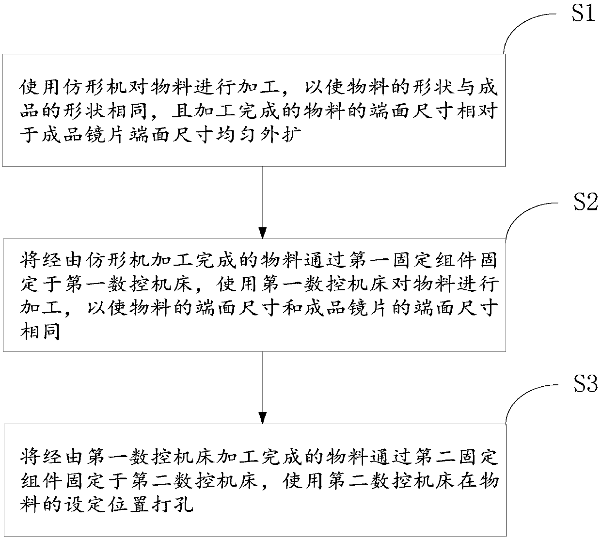
[0036] Such as figure 1 with figure 2 As shown, the camera lens processing method provided by the embodiment of the present invention includes:

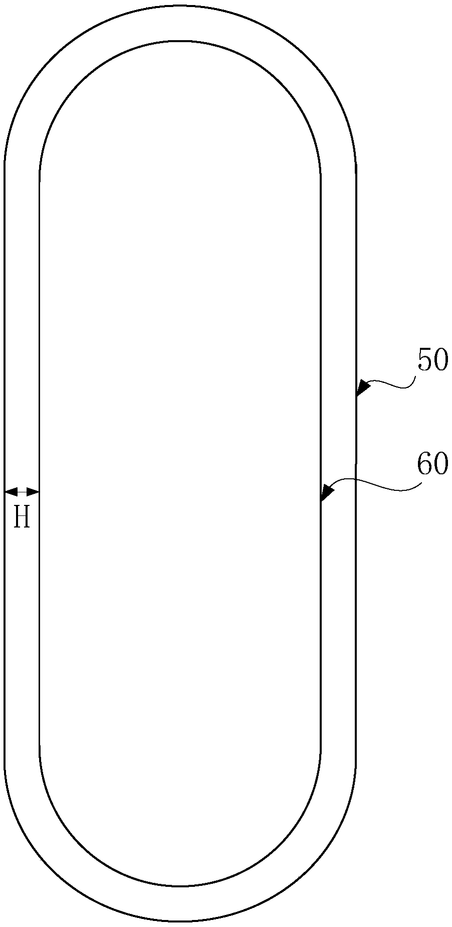
[0037] S1. Process the material 50 using a profiling machine so that the shape of the material 50 is the same as that of the finished product, and the size of the end surface of the processed material 50 is evenly expanded relative to the size of the end surface of the finished lens 60;

[0038] S2. Fix the material 50 processed by the profiling machine on the first numerical control machine tool through the first positioning assembly, and use the first numerical control machine tool to process the material 50 so that the end face size of the material 50 is the same as the end face size of the finished lens 60 ;

[0039] S3. Fix the material 50 processed by the first numerical control machine tool on the second numerical control machine tool through the second positioning component, and use the second numerical control machine too...

Embodiment 2

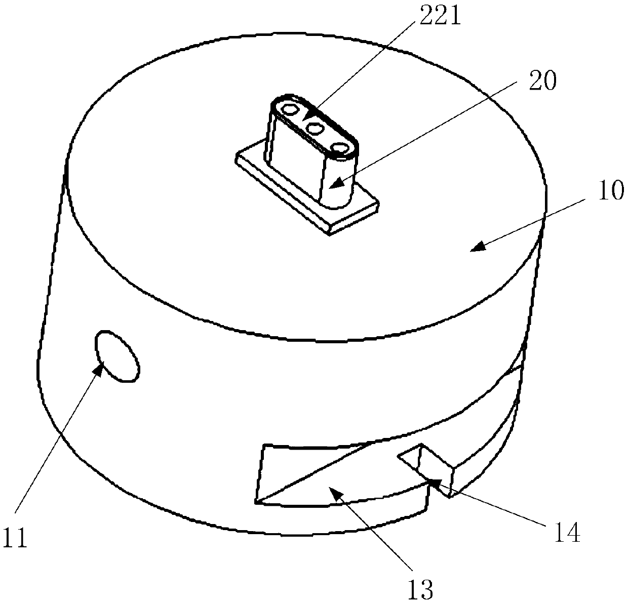
[0050] Embodiment 2 of the present invention will refer to the appended image 3 - attached Figure 9 , to further explain the structures of the first positioning component and the second positioning component used in the camera processing method provided in the first embodiment above.

[0051] The first positioning assembly is used to fix the material to the first numerical control machine tool, and the first positioning assembly is provided with a first suction hole 12 and a first suction mechanism connection port 11 communicating with the first suction hole 12 . During use, the first positioning assembly is fixed to the first CNC machining machine tool, and then the connecting pipe of the first suction mechanism is communicated with the first suction hole 12, and the material is placed on the top surface of the first positioning assembly, and the opening The first suction mechanism fixes the material with the first positioning component.

[0052] In a specific implementat...


PUM


Abstract

The invention provides a camera lens machining method, and relates to the technical field of camera lens machining. The method aims to solve the problems that the appearance error is large and the hole opening yield is low when a camera lens is machined. The camera lens machining method comprises the following steps that a material is machined by using a copying machine, so that the shape of the material is the same as that of a finished product, and the end face size of the machined material uniformly expands with respect to the size of the end face of the finished lens; the material machinedthrough the copying machine is fixed to a first numerical control machine tool through a first positioning assembly, then the first numerical control machine tool is used for machining the material,so that the end face size of the material and the end face size of the finished lens are the same; and the material machined through the first numerical control machine tool is fixed to a second numerical control machine tool through a second positioning assembly, and the second numerical control machine tool is used for punching the material at set positions. According to the camera lens machining method, the machined camera lens is small in appearance size error and high in hole opening yield.

Description

technical field [0001] The invention relates to the technical field of camera lens processing, in particular to a camera lens processing method. Background technique [0002] At present, when processing camera lenses, the outer contour of the material is first processed by a manual profiling machine, so that the cross-sectional shape and size of the material are the same as the shape and size of the finished product, and then holes are opened on the finished material by using a CNC machine tool . [0003] However, when the above-mentioned processing method is used to process the racetrack camera lens, and the length and width deviation ratio of the finished racetrack camera lens is relatively large (for example, the length and width deviation ratio reaches more than three times), but the cross-sectional area is small, use a manual profiling machine The shape of the processed material cannot reach the required error range, that is to say, using a manual profiling machine to ...

Claims


Application Information

Patent Timeline
Patent Type & Authority Applications(China)
IPC IPC(8): B24B13/00B24B13/005B24B9/14
CPCB24B9/14B24B9/146B24B13/0037B24B13/0055
Inventor 周群飞邓海平
Owner LENS TECH CHANGSHA
Why Eureka
Try Eureka