Driving circuit and its driving method, electronic ballast

A driving circuit and circuit technology, which are applied in the fields of electronic ballasts, driving circuits and driving methods thereof, can solve the problems of increasing the difficulty of circuit design, increasing the voltage stress of the post-stage inverter circuit, and increasing the cost, so as to improve the utilization of electric energy. Efficiency, reducing the number of conversion stages, reducing the size of the effect

Active Publication Date: 2022-04-01
FUJIAN RAYNEN TECH
View PDF23 Cites 0 Cited by
  • Summary
  • Abstract
  • Description
  • Claims
  • Application Information

AI Technical Summary

Problems solved by technology

However, this will also increase the voltage stress of the rear-stage inverter circuit, which increases the difficulty of circuit design. The voltage stress of the corresponding switch tube also needs to be selected to a higher value, which also increases the cost.

Method used


Image

  • Driving circuit and its driving method, electronic ballast
  • Driving circuit and its driving method, electronic ballast
  • Driving circuit and its driving method, electronic ballast

Examples


Embodiment Construction

[0028] The following will clearly and completely describe the technical solutions in the embodiments of the application with reference to the accompanying drawings in the embodiments of the application. Apparently, the described embodiments are only part of the embodiments of the application, not all of them. Based on the implementation manners in this application, all other implementation manners obtained by persons of ordinary skill in the art without making creative efforts belong to the scope of protection of this application.

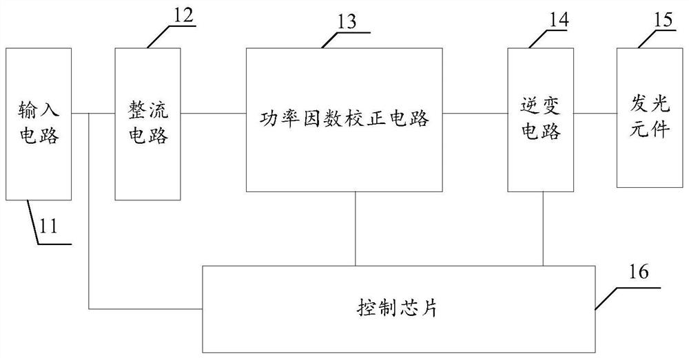
[0029] See figure 1 , is a schematic block diagram of the driving circuit of the present invention. The drive circuit includes: an input circuit 11, a rectifier circuit 12 coupled to the input circuit 11, a power factor correction circuit 13 coupled to the rectifier circuit 12, an inverter circuit 14 coupled to the power factor correction circuit 13 , coupled to the light-emitting element 15 of the inverter circuit 14 and coupled to the input circ...


PUM


Abstract

The invention provides a drive circuit, a drive method thereof, and an electronic ballast. The drive circuit includes an input circuit, a rectifier circuit coupled to the input circuit, a power factor correction circuit coupled to the rectifier circuit, and an inverter circuit coupled to the power factor correction circuit , The light-emitting element coupled to the inverter circuit and the control chip coupled to the input circuit, the power factor correction circuit and the inverter circuit; the input circuit is used to input AC voltage; the rectifier circuit is used to receive the AC voltage and output the first DC voltage; The factor correction circuit is used to receive the first DC voltage and output the second DC voltage; the control chip is used to receive the processed voltage signal of the AC voltage and the second DC voltage to output the first control signal to the power factor correction circuit and to the inverter circuit A second control signal is output; the inverter circuit is used for receiving the second DC voltage and converting the second DC voltage into an AC voltage to control the light-emitting element. In order to reduce the number of conversion stages of electric energy and improve the utilization rate of electric energy.

Description

technical field [0001] The present application relates to the technical field of electronic ballasts, in particular to a driving circuit, a driving method thereof, and an electronic ballast. Background technique [0002] In the commonly used HID (High intensity Discharge, electronic ballast), the relatively common input voltage range is generally single-phase AC 90Vac ~ 265Vac. Under this input voltage condition, the more mature circuit scheme of HID is generally: the AC The voltage is converted into a stable DC power through a step-up power factor correction circuit, and then converted into a suitable AC voltage and current through an inverter circuit to drive the HID lamp. Such a circuit scheme is simple, practical and cost-effective. [0003] However, when the application of electronic ballasts needs to be compatible with North American industrial electricity, the input grid types include 240V / 277V / 347V / 400V / 480V. Considering the voltage fluctuation of the grid, the inpu...

Claims


Application Information

Patent Timeline
Patent Type & Authority Patents(China)
IPC IPC(8): H05B41/288
CPCH05B41/2885
Inventor 徐志望陈高江陈云辉陈严锋
Owner FUJIAN RAYNEN TECH
Why Eureka
Try Eureka