Tissue ligation device for laparoscopic surgery

A surgical and ligation device technology, applied in the field of medical devices, can solve the problems of affecting the surgical process, cumbersome process, limited yarn material, etc., and achieves improved sterility, good biocompatibility, and blocking effect. clear effect

Active Publication Date: 2019-12-20
ZHEJIANG JINGJIA MEDICAL TECH CO LTD
View PDF8 Cites 2 Cited by
  • Summary
  • Abstract
  • Description
  • Claims
  • Application Information

AI Technical Summary

Problems solved by technology

Yarn is usually used for knotting, but in the actual operation process, there will be the following problems: (1) the degree of tightening after ligation cannot be judged, which is inconvenient for subsequent operations; (2) due to the limited material of yarn, knotting (3) During the ligation process, the thread may be broken due to the wear of the yarn thread and the knot pusher, which will affect the operation process.
However, this blocking technique will encounter some problems in actual clinical operation: (1) Some patients have hypertrophy of the mesorectum or large tumors, and the operating space is very limited in the narrow pelvis, so the vascular clip cannot be placed under the tumor; (2) ) Due to the limited size and model of the vascular clamp, the selection of an inappropriate vascular clamp will cause displacement or fall off due to poor occlusal force; in the prior art, the oval forceps are also used to directly close and block the intestinal tube, but the insertion of the oval forceps needs to be performed in the lower abdomen. Create another hole, put in the incision protective sleeve and establish pneumoperitoneum, the process is very cumbersome
However, ordinary nylon cable ties also have limitations in actual clinical operations: (1) Nylon cable ties need to hold a needle forceps or separating forceps with both hands to encircle and ligate the intestine, and one end clamps the lock of the cable tie , the other end clamps the tail of the zigzag belt and passes through the lock head. Since the lock head of the nylon cable tie is very small, the step of passing through the lock head needs repeated attempts, which delays the operation process
(2) After wrapping the ligation, it is necessary to tighten the tie to block the intestine. Due to two-handed operation, the force point of the needle holding forceps or separating forceps to tighten the serrated belt and withstand the lock is not on a straight line. Nylon cable ties cannot be tightly tightened in the narrow operating space, and the intestinal tract cannot be effectively blocked

Method used


Image

  • Tissue ligation device for laparoscopic surgery
  • Tissue ligation device for laparoscopic surgery
  • Tissue ligation device for laparoscopic surgery

Examples


Embodiment 1

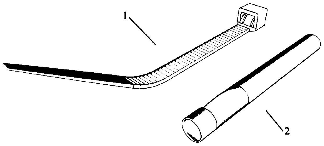
[0034] Such as Figure 1-7 As shown, the tissue ligation device for laparoscopic surgery in this embodiment includes two parts, namely a ligation strip 1 and a retraction rod 2 .

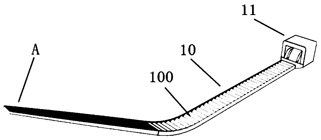
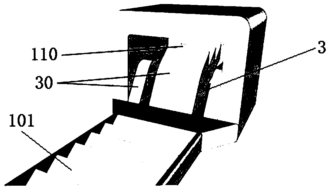
[0035] Such as figure 2 and 3 As shown, the ligation strip 1 of this embodiment includes a rack 10, the upper surface of the rack 10 has a first anti-skid tooth array 100, and the first anti-skid tooth array 100 includes several number of the first anti-skid tooth array 100 arranged at equal intervals along its length direction. An anti-slip tooth 101, meeting the size requirements of various lesion tissues. The right end of tooth bar 10 is connected with tooth cavity 11, and tooth cavity 11 is the cavity structure of both ends opening, comprises plug-in end (being the left end of tooth cavity) and protruding end (being the right end of tooth cavity); At least one second anti-skid tooth 110 is engaged with the first anti-skid tooth 101 to limit. The left end of the rack 10 is used to insert the...

Embodiment 2

[0044] The difference between the laparoscopic surgery tissue ligation device of the present embodiment and the first embodiment is:

[0045] In Embodiment 1, at least one of the slope structure of the insertion end of the tooth cavity and the design of the guide slope of the retracting rod is omitted, and the structure of the ligation device is simplified to meet the requirements of different applications.

[0046] Other structures can refer to Embodiment 1.

Embodiment 3

[0048] The difference between the laparoscopic surgery tissue ligation device of the present embodiment and the first embodiment is:

[0049] The tissue ligation device for laparoscopic surgery in this embodiment can also be used in laparotomy. The structure of the retracting rod is not limited to the round rod structure, and its cross-section can also be triangular, quadrangular, elliptical and other structures to meet the needs of different users.

[0050] Other structures can refer to Embodiment 1.


PUM


Abstract

The invention belongs to the technical field of medical instruments, and particularly relates to a tissue ligation device for laparoscopic surgery. The tissue ligation device comprises a ligation barand a gathering rod, wherein the ligature bar includes a rack, a surface of the rack is provided with a plurality of first anti-skid teeth, and the first anti-skid teeth are distributed along a lengthdirection of the rack; a first end of the rack is connected with a tooth cavity, and at least one second anti-skid tooth for meshing and limiting with the first anti-skid teeth is arranged in the tooth cavity; a second end of the rack is inserted into the tooth cavity and movably matched with the tooth cavity; when the second end of the rack moves to a target position, the corresponding first anti-skid teeth on the rack are meshed and limited with the at least one second anti-skid tooth in the tooth cavity so as to perform ligation on focus tissues; the gathering rod is provided with a guidehole; and the gathering rod is used for abutting against the tooth cavity, so that the second end of the rack penetrates through the guide hole and the gathering rod guides movement of the rack through the guide hole. During the use of the tissue ligation device in the laparoscopic surgery, especially laparoscopic radical rectal cancer surgery, the tissue ligation device can quickly and effectively ligature, tighten and block intestinal canals, and facilitate irrigation of the intestinal canals to ensure a tumor-free principle.

Description

technical field [0001] The invention belongs to the technical field of medical devices, and in particular relates to a tissue ligation device for laparoscopic surgery. Background technique [0002] In laparoscopic surgery, there is still a lack of ideal instruments for ligation and blocking of tissues, such as diseased stomach and intestines. Yarn is usually used for knotting, but in the actual operation process, there will be the following problems: (1) the degree of tightening after ligation cannot be judged, which is inconvenient for subsequent operations; (2) due to the limited material of yarn, knotting (3) During the ligation process, the wear of the yarn line and the knot pusher may cause the line to break and affect the operation process. Especially in laparoscopic radical resection of rectal cancer, the existing problems are far from being completely resolved, such as the principle of tumor-free operation. In order to prevent anastomotic recurrence after sphincter...

Claims


Application Information

Patent Timeline
Patent Type & Authority Applications(China)
IPC IPC(8): A61B17/12A61B17/3205A61B17/34
CPCA61B17/12013A61B17/32056A61B17/3468A61B17/3478
Inventor 朱剑锋方草华菲
Owner ZHEJIANG JINGJIA MEDICAL TECH CO LTD
Why Eureka
Try Eureka