An energy-saving and efficient thermal desorption system for soil remediation
A soil remediation and thermal desorption technology, which is applied in the field of energy-saving and high-efficiency thermal desorption systems for soil remediation, can solve the problems of rapid heat loss and low utilization rate of heat of soil thermal desorption, so as to improve thermal desorption efficiency and avoid heat Loss, easy to collect effect
- Summary
- Abstract
- Description
- Claims
- Application Information
AI Technical Summary
Problems solved by technology
Method used
Image
Examples
Embodiment 1
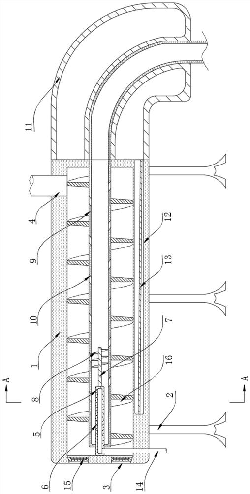
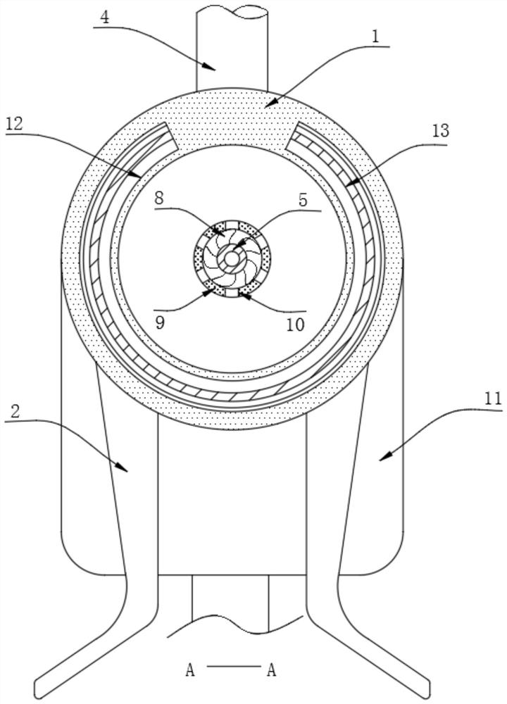
[0024] refer to Figure 1-2 , an energy-saving and high-efficiency thermal desorption system for soil remediation, comprising a cylindrical thermal desorption box 1, a plurality of groups of brackets 2 for supporting the thermal desorption box 1 are symmetrically fixed to the lower side of the outer wall of the thermal desorption box 1, and A group of discharge holes 3 are provided through the side wall of the stripping box 1, and a feed pipe 4 is inserted through the circumferential side wall of the thermal stripping box 1 away from the end of the discharge hole 3, and the end of the thermal stripping box 1 close to the discharge hole 3 The inner wall of the heat removal box 1 is welded with a fixed tube 5, and the circumferential side wall of the heat removal box 1 is inserted with an air inlet pipe 14 communicating with the inside of the fixed tube 5. The end of the cylinder 5 away from the discharge hole 3 is rotatably connected with a rotating shaft 7, and a group of driv...
Embodiment 2
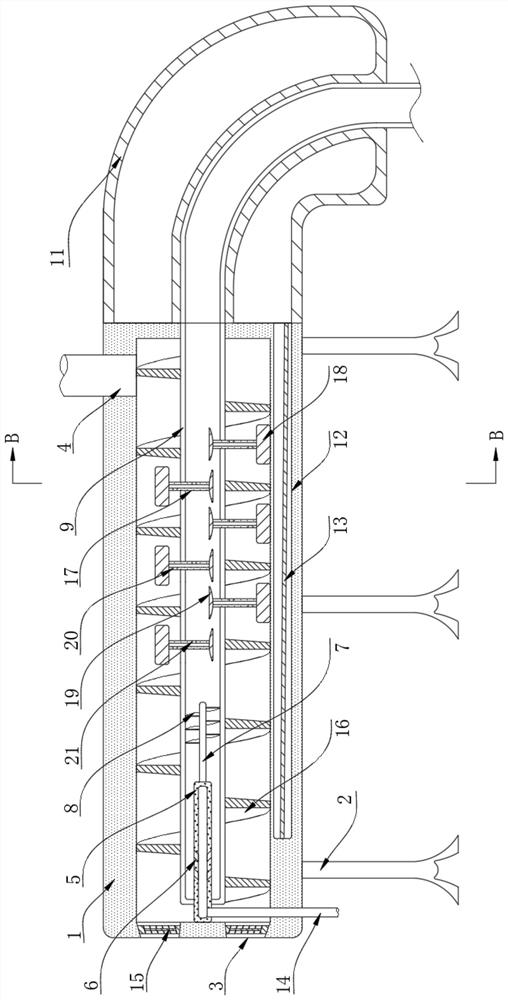
[0032] The difference between this embodiment and Embodiment 1 lies in the difference of the backflow device. In the present embodiment, the backflow device includes a plurality of ventilation pipes 17 that are slidably connected to the side walls of the auger rotating rod 9, and each ventilation pipe 17 is located on the side wall of the auger rotating rod. One end of the 9 inside is welded with a wing plate 19, and each vent pipe 17 is welded with a scraper 18 at one end outside the auger rotating rod 9, and the side wall of each vent pipe 17 is provided with a plurality of air inlet holes 20 and outlets. The air hole 21 and the air outlet hole 21 are closer to the inside of the auger rotating rod 9 than the corresponding air inlet hole 20; There is an air pressure difference between the two sides of the wing plate 19, so that the wing plate 19 can push the lower scraper 18 to insert into the soil.
[0033] When the high-temperature steam flows inside the auger rotating rod ...
PUM
 Abstract
Description
Claims
Application Information
 - R&D
- Intellectual Property
- Life Sciences
- Materials
- Tech Scout
- Unparalleled Data Quality
- Higher Quality Content
- 60% Fewer Hallucinations
Browse by: Latest US Patents, China's latest patents, Technical Efficacy Thesaurus, Application Domain, Technology Topic, Popular Technical Reports.
© 2025 PatSnap. All rights reserved.Legal|Privacy policy|Modern Slavery Act Transparency Statement|Sitemap|About US| Contact US: help@patsnap.com


