Centrifugal pump housing casting technology

A casting process and centrifugal pump technology, applied in the field of centrifugal pump casing casting process, can solve the problems of small support area of ​​reinforcement ribs, poor support effect of molding sand, failure of reinforcement ribs to form a support structure, etc., so as to increase stability and applicability Effect

Active Publication Date: 2019-12-20
河南齐盛威实业有限公司
View PDF6 Cites 2 Cited by
  • Summary
  • Abstract
  • Description
  • Claims
  • Application Information

AI Technical Summary

Problems solved by technology

[0003] The basic structure of the centrifugal pump is composed of six parts: impeller, casing, pump shaft, bearing, sealing ring and stuffing box. The casing of the centrifugal pump is processed by casting. The casing of the centrifugal pump is cast due to its The shape and structure are relatively complex, which can easily lead to deformation and dislocation of the cavity of the molding sand in the upper sand box, which will lead to problems such as poor casting effect of the centrifugal pump shell. Add reinforcing ribs to strengthen the support. The problems of adding reinforcing ribs in the existing upper sand box are as follows:
[0004] The supporting area of ​​the reinforcing ribs is small, and the supporting effect on the molding sand in the upper sand box is poor; and the position adjustment of the reinforcing ribs is relatively cumbersome, and the casting may be affected when supporting different types of shells, and the forming of the reinforcing ribs cannot be achieved. An overall support structure that makes it less stable

Method used


Image

  • Centrifugal pump housing casting technology
  • Centrifugal pump housing casting technology
  • Centrifugal pump housing casting technology

Examples


Embodiment Construction

[0035] The embodiments of the present invention will be described in detail below with reference to the accompanying drawings, but the present invention can be implemented in many different ways defined and covered by the claims.

[0036] Such as Figure 1 to Figure 5 As shown, a centrifugal pump casing casting process includes the following steps:

[0037] S1. Casting preparation: Put the molding sand for casting into the sand mixer for sand mixing treatment, and clean the aluminum pattern of the centrifugal pump casing with a brush to remove the sundries on the surface and in the cavity;

[0038] S2. Lower molding sand molding: put the molding sand mixed in step S1 into the lower flask, and carry out molding processing on the molding sand in the lower flask through the shape of the centrifugal pump casing;

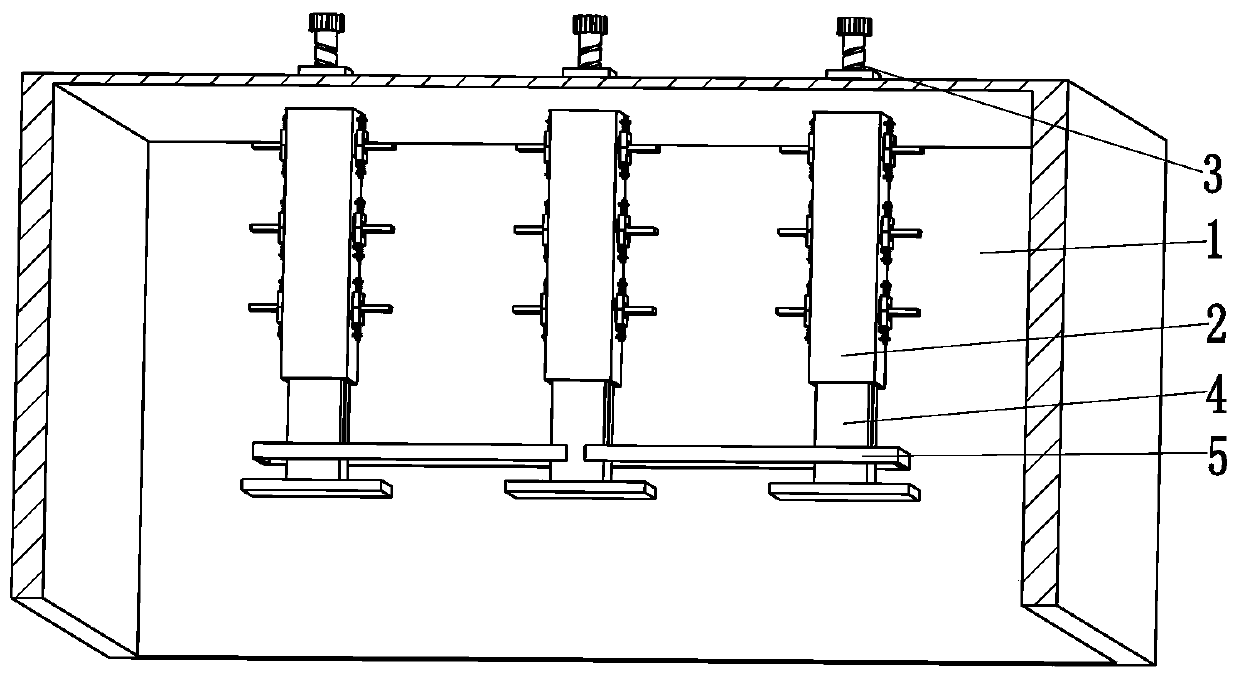
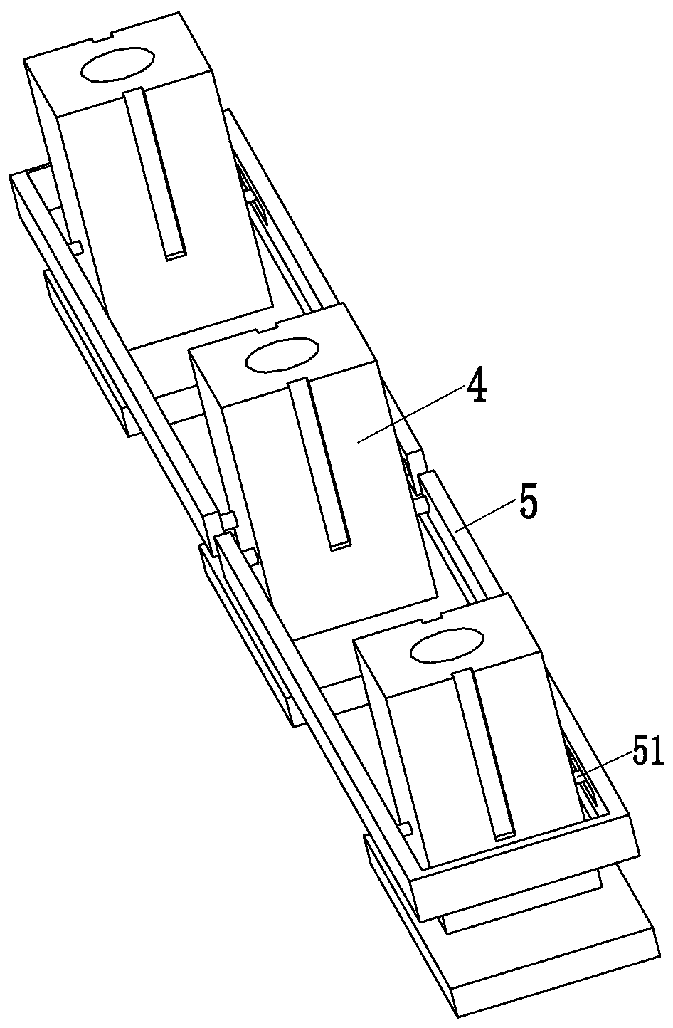
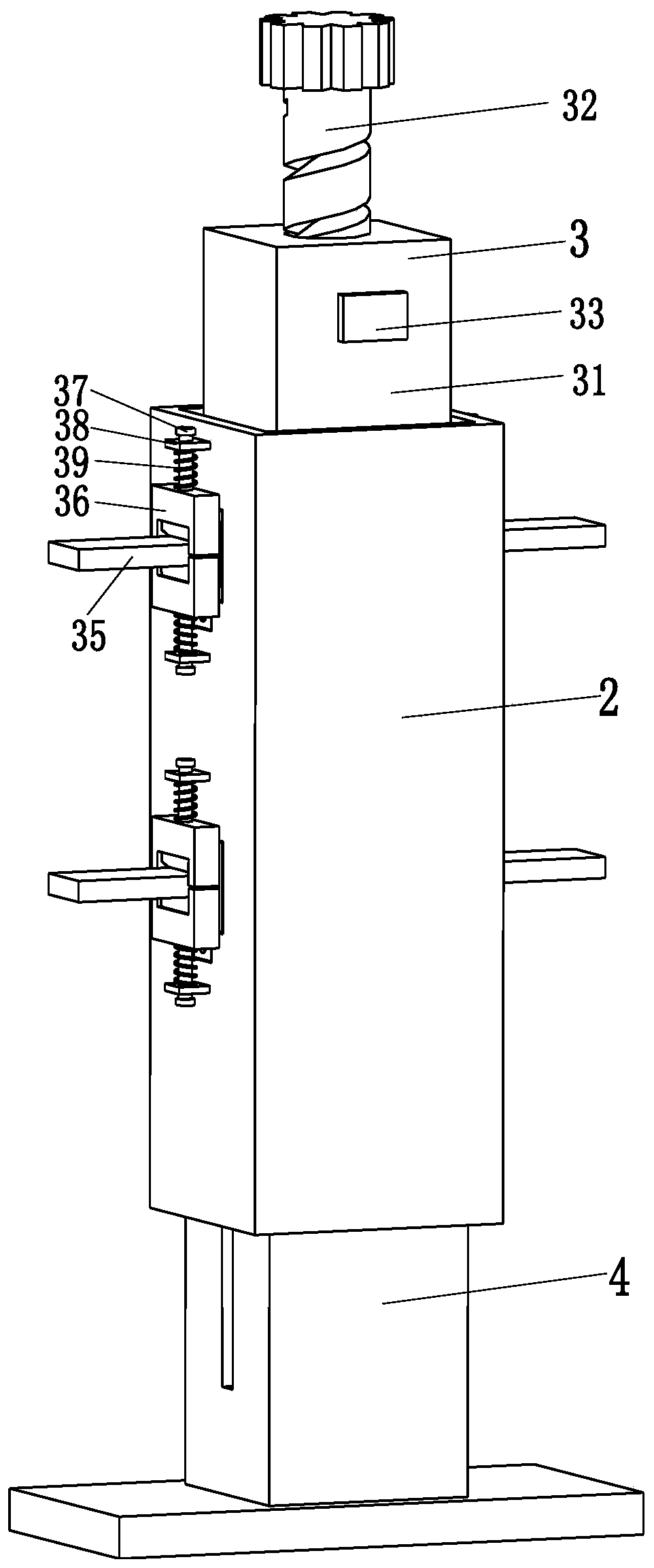
[0039] S3. Modeling of the upper sand box: Firstly, the inner support column 2 is evenly installed in the square hole of the upper sand box 1, and then the telescopic m...


PUM


Abstract

The invention relates to a centrifugal pump housing casting technology. The casting technology comprises the following steps: S1, casting preparation; S2, molding of lower molding sand; S3, molding ofan upper sand tank: firstly, uniformly installing inner support columns in square holes of the upper sand tank, then adjusting telescopic mechanisms according to the structure of the pump surface tomove moving columns to proper positions, and then putting the molding sand into the upper sand tank and putting a mold to mold the molding sand; S4, molding sand setting; S5, sand tank casting; S6, housing grinding. Each telescopic mechanism comprises an adjusting column, a threaded rod, a locking frame, locking springs and turning branch chains. The problems that reinforcing ribs are added to theexisting upper sand tank, the supporting effect on the molding sand in the upper sand tank is poor due to small supporting area of the reinforcing ribs and stability of the reinforcing ribs is poor because casting may be affected when the reinforcing ribs are used for supporting housings of different types, and an integral supporting structure cannot be formed between the reinforcing ribs can besolved.

Description

technical field [0001] The invention relates to the technical field of pump body processing, in particular to a casting process for a centrifugal pump casing. Background technique [0002] Centrifugal pumps are used to transport slurry containing solid particles, and can be widely used in electric power, metallurgy, coal, building materials and other industries, such as hydraulic ash removal in thermal power plants, slurry transportation in metallurgical beneficiation plants, coal slurry and heavy medium transportation in coal washing plants, etc. [0003] The basic structure of the centrifugal pump is composed of six parts: impeller, casing, pump shaft, bearing, sealing ring and stuffing box. The casing of the centrifugal pump is processed by casting. The casing of the centrifugal pump is cast due to its The shape and structure are relatively complex, which can easily lead to deformation and dislocation of the cavity of the molding sand in the upper sand box, which will lea...

Claims


Application Information

Patent Timeline
Patent Type & Authority Applications(China)
IPC IPC(8): B22C9/02B22C9/22B22C21/14
CPCB22C9/02B22C9/22B22C21/14
Inventor 郭东东姚孝明
Owner 河南齐盛威实业有限公司
Why Eureka
Try Eureka