
A welding machine for valve production

A welding machine and valve technology, applied in welding equipment, auxiliary welding equipment, welding/cutting auxiliary equipment, etc., can solve the problems of human body burns, low welding quality, slow moving speed of the welding gun, etc., to facilitate collection, improve practicability, The effect of improving the effect of flue gas purification

Active Publication Date: 2020-01-24
SHANDONG ZHUCHENG JIANHUA VALVE MFG
View PDF10 Cites 1 Cited by
  • Summary
  • Abstract
  • Description
  • Claims
  • Application Information

AI Technical Summary

Problems solved by technology

[0002] As we all know, valves need to be welded during production and processing. The existing welding methods mainly use manual welding. During manual welding, the stability of the hand is poor, and the distance between the welding torch and the position to be welded on the valve changes. , leading to poor uniformity of solder joints, poor strength of the valve after welding, and low welding quality. At the same time, when the welding torch is welding the valve, the welding torch moves slowly, the welding time is long, the work efficiency is low, and the physical strength of the human body is exhausted. Larger, when the welding torch is working, the temperature at the bottom of the welding torch is high, which is easy to cause burns to the human body

Method used


Image

  • A welding machine for valve production
  • A welding machine for valve production
  • A welding machine for valve production

Examples


Embodiment Construction

[0018] The specific implementation manners of the present invention will be further described in detail below in conjunction with the accompanying drawings and embodiments. The following examples are used to illustrate the present invention, but are not intended to limit the scope of the present invention.

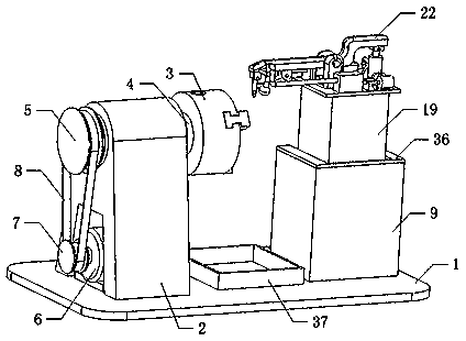
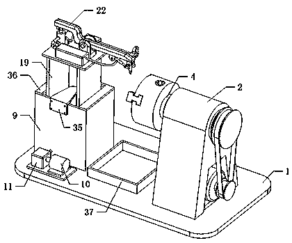
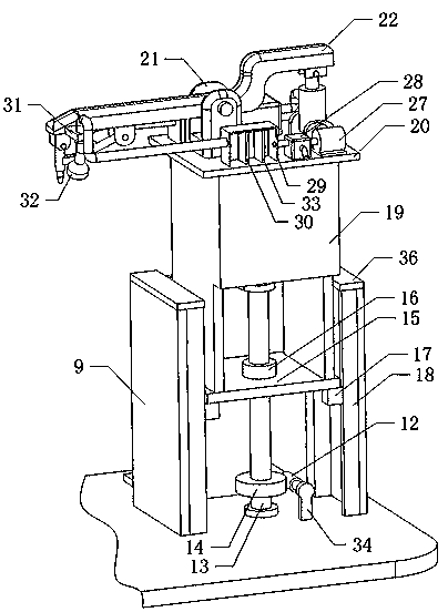
[0019] Such as Figure 1 to Figure 4 As shown, a welding machine for valve production of the present invention, when it is working, opens the chuck 3, installs the valve on the right end of the chuck 3 and fixes the valve through the chuck 3, and opens the first motor 6 , the first motor 6 drives the second pulley 7 to rotate through the first rotating shaft, and the second pulley 7 drives the first pulley 5, the main shaft 4, the chuck 3 and the valve to rotate synchronously through the belt 8, and the second motor 10 is opened, and the second motor 10 drives the speed reducer 11 to run through the second shaft, the speed reducer 11 drives the first helical gear 12 to ro...


PUM


Abstract

The invention relates to the technical field of mechanical equipment, in particular to a welding machine for valve production. Through automatic welding of a valve, the welding strength of the valve can be effectively improved, the quality of the valve is improved, at the same time, the welding speed of the valve is increased, the work efficiency is effectively improved, and when the welding machine is in operation, a human body can be far away from the welding machine, so that the high temperature generated by a welding gun during welding is effectively prevented from causing scald to the human body, and the practicality and reliability are improved. The welding machine comprises a working table, a chuck bracket, a chuck, a spindle, a first belt pulley, a first motor, a second belt pulley, a belt, a casing, a second motor, a speed reducer, a first spiral gear and a lead screw, wherein the left side of the top end of the working table is connected with the bottom end of the chuck bracket, the chuck is located at the upper right of the chuck bracket, and the left end of the chuck is connected with the right end of the spindle.

Description

technical field [0001] The invention relates to the technical field of mechanical equipment, in particular to a welding machine used for valve production. Background technique [0002] As we all know, valves need to be welded during production and processing. The existing welding methods mainly use manual welding. During manual welding, the stability of the hand is poor, and the distance between the welding torch and the position to be welded on the valve varies. , leading to poor uniformity of solder joints, poor strength of the valve after welding, and low welding quality. At the same time, when the welding torch is welding the valve, the welding torch moves slowly, the welding time is long, the work efficiency is low, and the physical strength of the human body is exhausted. Larger, when the welding torch is working, the temperature at the bottom of the welding torch is high, which is easy to cause burns to the human body. Contents of the invention [0003] In order to...

Claims


Application Information

Patent Timeline
Patent Type & Authority Patents(China)
IPC IPC(8): B23K37/00B23K37/04B23K37/02B08B15/04B01D46/10
CPCB01D46/10B08B15/04B23K37/00B23K37/0211B23K37/0443
Inventor 王华梅
Owner SHANDONG ZHUCHENG JIANHUA VALVE MFG
Learn More