
A device for removing slag at the welding joint of grid frame

A welding joint and slag cleaning technology, applied in grinding/polishing safety devices, metal processing equipment, manufacturing tools, etc., can solve the problems of low recycling value of pure impurity particles, no recycling value, affecting recycling, etc. Reduced grinding spatter, ease of movement and improved safety

Active Publication Date: 2020-11-24
HEBEI CONSTR GRP CO LTD
View PDF9 Cites 0 Cited by
  • Summary
  • Abstract
  • Description
  • Claims
  • Application Information

AI Technical Summary

Problems solved by technology

[0002] Various welding forms can be used for welding the grid. During welding, excess welding slag will be generated at the welding position. The excess welding slag needs to be ground to expose the scale-like surface to improve the welding strength. It is easy to check after grinding Welding bit quality, most of the welding slag is iron, and the welding slag particles are formed after grinding, which can be recycled when the welding slag is cleaned, but in different environments and different welding processes, the ground welding slag particles are also It may contain other impurities, and the recycling value of pure impurity particles is low or even has no recycling value, which will affect the later recycling
The traditional recycling method adopts the collection box to undertake or negative pressure extraction, the collection effect is poor, and the welding slag splashes and wastes more

Method used


Image

  • A device for removing slag at the welding joint of grid frame
  • A device for removing slag at the welding joint of grid frame
  • A device for removing slag at the welding joint of grid frame

Examples


Embodiment Construction

[0027] The present invention will be further described in detail below in conjunction with the accompanying drawings and specific embodiments.

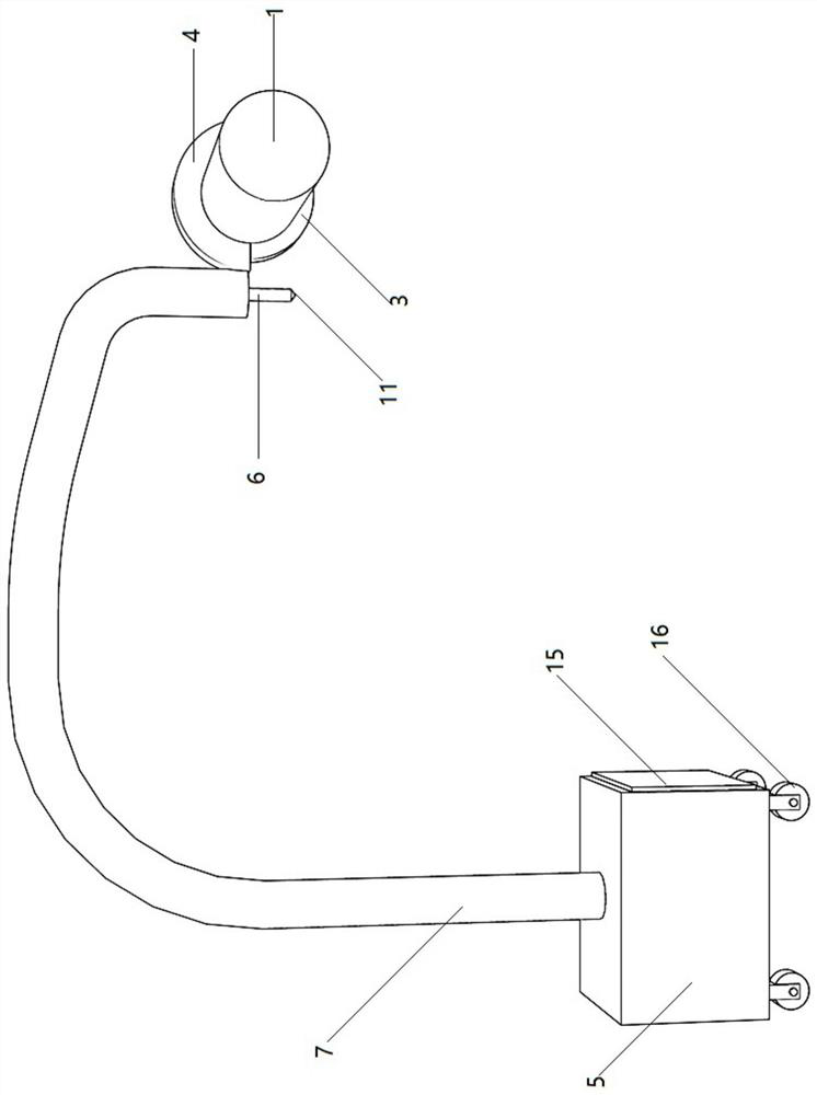
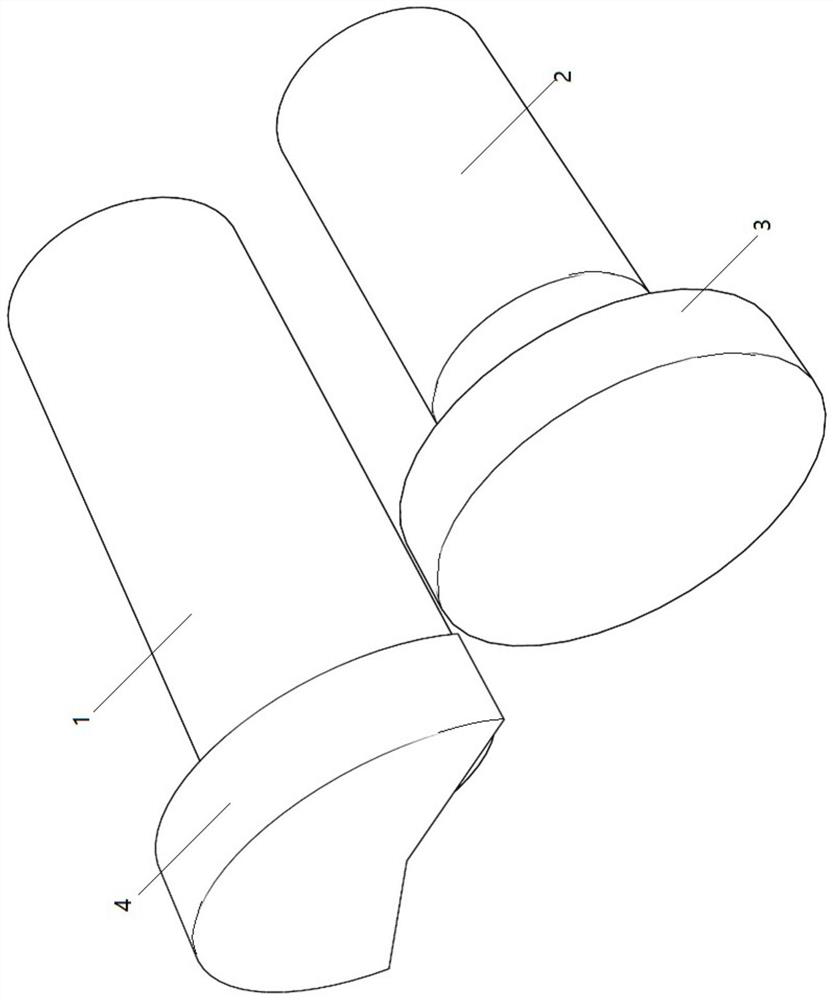
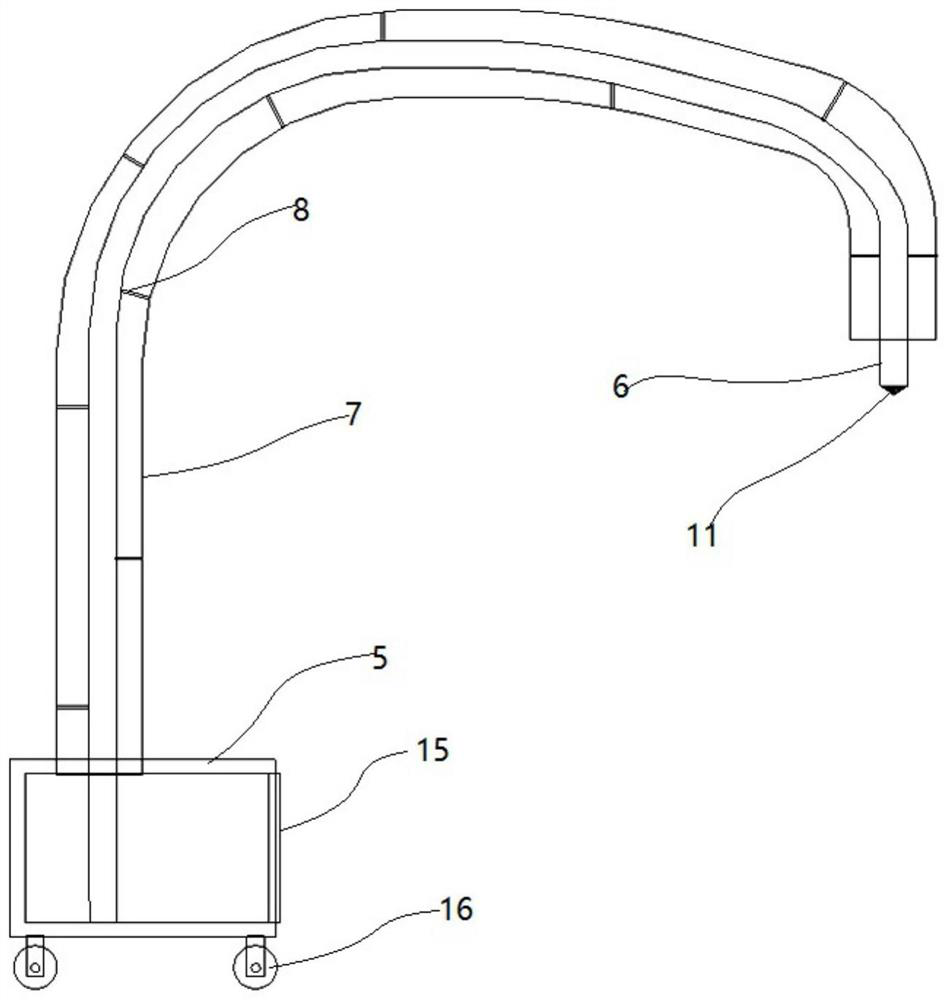
[0028] like Figure 1-7 As shown, a slag removal device for grid welding joints includes a grinding mechanism and a collecting mechanism; the grinding mechanism includes a mounting shell 1; a driving motor 2 is installed in the front of the mounting shell 1; the output end of the driving motor 2 A grinding wheel 3 is installed; a protective shell 4 is fixedly installed at the front end of the installation shell 1; the grinding wheel 3 is in the protective shell 4; the lower part of the grinding wheel 3 is outside the protective shell 4; the collection mechanism includes a collection box 5, a shaping tube 6 and A plurality of electromagnetic transportation modules; the upper end of the collection box 5 is connected with a guide tube 7; the lower end of the guide tube 7 is fixedly connected to the upper end of the collection box 5, the ...


PUM


Abstract

The invention discloses a slag cleaning device for a grid frame welding port, and relates to the technical field of slag cleaning. The slag cleaning device comprises a grinding mechanism and a collection mechanism; the grinding mechanism comprises a mounting shell, and a grinding wheel is arranged at the output end of a driving motor; the collection mechanism comprises a collection box, a shapingpipe and a plurality of electromagnetic transport modules, and a guiding pipe is connected with the upper end of the collection box; the lower end of the shaping pipe extends into the collection box,the top of the shaping pipe is outside the guide pipe, and the top of the shaping pipe faces downward; the plurality of electromagnetic transport modules are uniformly and fixedly arranged in the shaping pipe, and each electromagnetic transport module comprises an integrated shell fixedly connected with the inner wall of the shaping pipe; and three electromagnets are fixedly installed in the axialdirection in the integrated shell, and a conical guide cone is fixed at the top end of the integrated shell at the top end. The slag cleaning device has the beneficial effects that the grinding mechanism is used for cleaning the excess part of the welding position, and the collection mechanism performs transportation and collection of the ground welding slag through magnetic attraction.

Description

technical field [0001] The invention relates to the technical field of welding slag cleaning. Background technique [0002] Various welding forms can be used for welding the grid. During welding, excess welding slag will be generated at the welding position. The excess welding slag needs to be ground to expose the scale-like surface to improve the welding strength. It is easy to check after grinding Welding bit quality, most of the welding slag is iron, and the welding slag particles are formed after grinding, which can be recycled when the welding slag is cleaned, but in different environments and different welding processes, the ground welding slag particles are also It may contain other impurities, and the recycling value of pure impurity particles is low or even has no recycling value, which will affect the later recycling. The traditional recycling method adopts the collection box to undertake or negative pressure extraction, the collection effect is poor, and the weld...

Claims


Application Information

Patent Timeline
Patent Type & Authority Patents(China)
IPC IPC(8): B24B9/04B24B55/06B24B27/00
CPCB24B9/04B24B27/0007B24B55/06
Inventor 刘三奔
Owner HEBEI CONSTR GRP CO LTD
Learn More