Eureka AIR delivers breakthrough ideas for toughest innovation challenges, trusted by R&D personnel around the world.

Glass kiln arch top repair auxiliary device

A glass furnace and auxiliary device technology, applied in glass furnace equipment, glass manufacturing equipment, manufacturing tools, etc., can solve the problems of easy melting, slow cooling of hot feed, dripping, etc., to achieve overall structural stability and improve speed. , the effect of easy repair

Pending Publication Date: 2019-12-20
安徽通显新材料股份有限公司
View PDF0 Cites 0 Cited by
  • Summary
  • Abstract
  • Description
  • Claims
  • Application Information

AI Technical Summary

Problems solved by technology

[0003] The technical problem to be solved by the present invention is: the cooling of the existing hot patch material is relatively slow, and it is easy to melt under the action of high-temperature corrosive gas, which affects the repair effect, and also drops into the pool to affect the product quality. The internal pressure is stronger than the external atmospheric pressure. When the repair material is blocked, the repair material will often be ejected under the action of the internal pressure, which will further affect the repair effect

Method used


Image

  • Glass kiln arch top repair auxiliary device
  • Glass kiln arch top repair auxiliary device

Examples


Embodiment 1

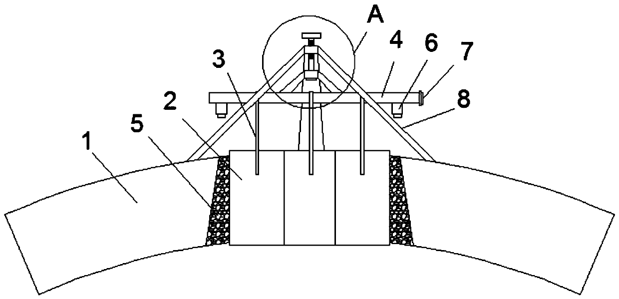
[0021] see Figure 1-2 , an auxiliary device for repairing the roof of a glass kiln, including a hanging pipe 4 for hanging silica bricks 2, and the silicon bricks 2 are hung on the hanging pipe 4 through a prefabricated hanging rod 3 connected thereto; the hanging pipe 4 One end is sealed, and the other end of the hanging pipe 4 communicates with the external gas supply pipeline through the connector 7; the lower end of the hanging pipe 4 is provided with a plurality of nozzles 6, and the spraying direction of the nozzles 6 is directly facing the dome 1 and the silica brick 2 The repair material 5 between them; the hanging pipe 5 is placed on the outer surface of the dome 1 through a tripod 8, and the upper end of the tripod 8 is fixedly connected with the hanging pipe 4 through a connecting rod 14.

[0022] The working principle of the present invention is: the method for realizing the repair of the light transmission hole of the dome 1 by the present application comprises t...

Embodiment 2

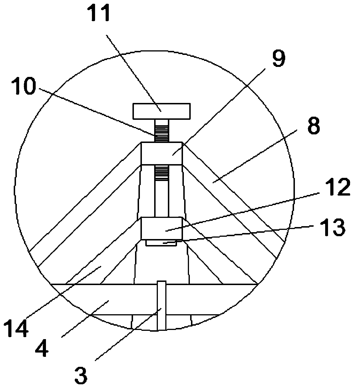
[0028] see Figure 1-2 , the same as Embodiment 1, the difference is that a height adjustment device is added, and the height adjustment device includes a first sleeve 9 fixed on the upper end of the tripod 8 and a second sleeve 12 on the upper end of the connecting rod 14, the first A threaded screw 10 is provided inside the sleeve 9 , the screw 10 passes through the second sleeve 12 and extends below the second sleeve 12 to connect with the stopper 13 , and a rotary handle 11 is provided at the upper end of the screw 10 .

[0029] Through the setting of the height adjustment device, on the one hand, the installation height of the silica brick 2 can be adjusted to match the height of the dome 1; Pressing down on the tripod 8 under action makes the overall structure stable.

[0030] Preferably, the lower ends of the three legs of the tripod 8 are all provided with fixing blocks (not shown), so as to further improve its overall stability.


PUM


Abstract

The invention discloses a glass kiln arch top repair auxiliary device, which comprises a hanging pipe for hanging silicon bricks, wherein the silicon bricks are hung on the hanging pipe through prefabricated hanging rods connected with the silicon bricks; one end of the hanging pipe is sealed, and the other end of the hanging pipe is communicated with an external gas supply pipeline through a connecting head; a plurality of spray heads are arranged at the lower end of the hanging pipe, and the spraying direction of the spray heads directly faces the repair material between the crown top and the silicon brick. According to the invention, the repair material is cooled by an air cooling method, so that the repair material is not easy to be ablated, and the curing speed of the repair materialis improved, so as to prevent that the ablation of the repair material falls into a glass kiln to affect the quality of a glass solution; the high-pressure gas is blown on the outer surface of the repair material, so that the internal and external pressures at the repair material are the same, the repair material is prevented from being ejected under the action of the internal pressure, and the repair effect is improved.

Description

technical field [0001] The invention relates to the field of glass kilns, in particular to an auxiliary device for repairing the roof of a glass kiln. Background technique [0002] The glass preparation process requires high-temperature melting, and the furnace, as a high-temperature melting device for glass, tends to form fire holes on the roof after working for a long time, especially when the holes are large, which is a threat to the safe operation of the furnace and stable production. . Existing kilns are generally overhauled in a cycle of two or four years. When the fire holes appear during the non-overhaul period, the existing treatment method is to use repairing materials to block them. The outstanding problem of this plugging method is : 1) The cooling of the repair material is slow, and it is prone to melting under the action of high-temperature corrosive gas at 1560 °C in the kiln, which affects the repair effect, and also drips into the pool to affect the product...

Claims


Application Information

Patent Timeline
IPC IPC(8): C03B5/16C03B5/42
CPCC03B5/16C03B5/42
Inventor 陈梅英
Owner 安徽通显新材料股份有限公司
Why Eureka
Eureka Blog
Learn More