Lower tube base buoyancy locking mechanism of lead-based reactor fuel component

A lead-based reactor and locking mechanism technology, applied in the directions of reactor fuel elements, fuel element assembly, reactors, etc., can solve the problem of fuel assemblies moving up and down, difficult to withstand high temperature, high corrosion and high radiation environment seismic load of liquid lead-bismuth coolant Comprehensive effect and other problems to achieve the effect of avoiding corrosion

Active Publication Date: 2019-12-20
INST OF MODERN PHYSICS CHINESE ACADEMY OF SCI
View PDF11 Cites 2 Cited by
  • Summary
  • Abstract
  • Description
  • Claims
  • Application Information

AI Technical Summary

Problems solved by technology

Although this locking mechanism takes advantage of the large buoyancy of the liquid lead-bismuth alloy, it does not realize the locking of the fuel assembly in the true sense, and the fuel assembly still has the possibility of moving up and down, especially in earthquake conditions. The fuel assembly moves up and down, causing the lock slider to slide to the unlocked position, causing the fuel assembly to be unlocked
[0007] As mentioned above, the existing fuel assemblies are difficult to withstand the combined effect of high temperature, high corrosion, high radiation environment in the reactor and seismic load of the liquid lead-bismuth coolant in the lead-based reactor

Method used


Image

  • Lower tube base buoyancy locking mechanism of lead-based reactor fuel component
  • Lower tube base buoyancy locking mechanism of lead-based reactor fuel component
  • Lower tube base buoyancy locking mechanism of lead-based reactor fuel component

Examples


Embodiment Construction

[0027] Preferred embodiments of the present invention will be described in detail below with reference to the accompanying drawings, so as to better understand the purpose, features and advantages of the present invention. It should be understood that the embodiments shown in the drawings are not intended to limit the scope of the present invention, but only to illustrate the essence of the technical solutions of the present invention.

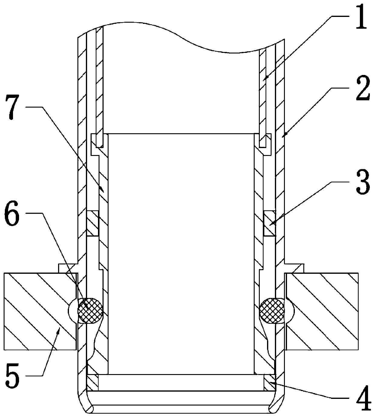
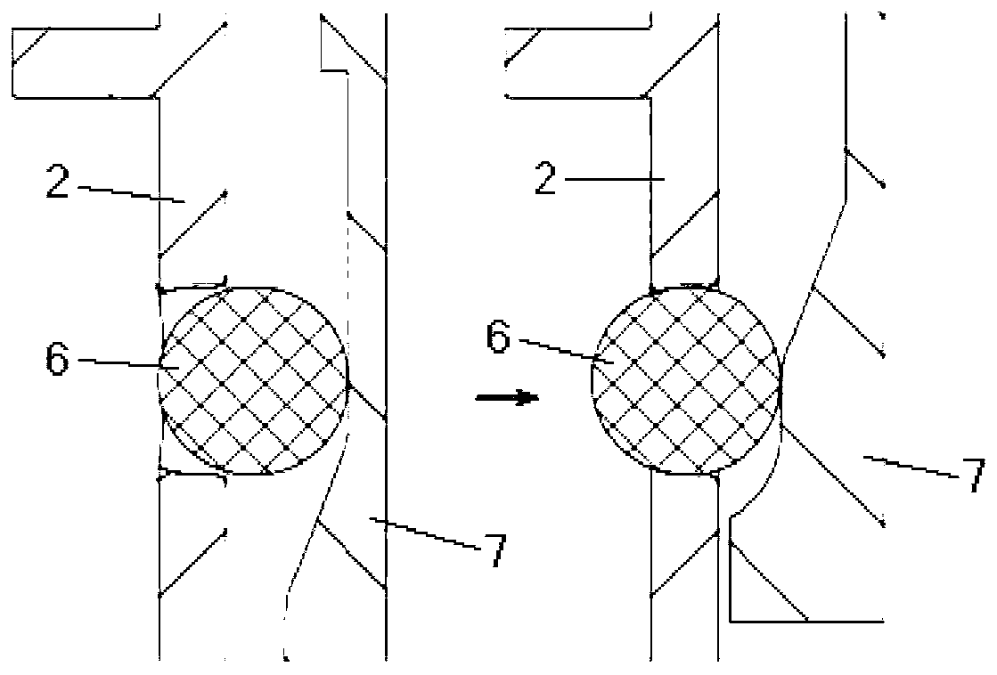
[0028] like figure 1As shown, the lower nozzle buoyancy locking mechanism of the lead-based reactor fuel assembly provided by the present invention includes: a core grid plate 5, and a through hole is provided on the core grid plate 5, and the holes in the core grid plate 5 There are several locking grooves on the inner wall along the circumferential direction; the lower pipe seat 2 is a cylindrical shell and forms the outer boundary of the buoyancy locking mechanism 100 of the lower pipe seat, and is used for positioning and inserting into th...


PUM


Abstract

The invention relates to a lower tube base buoyancy locking mechanism of a lead-based reactor fuel component. The mechanism comprises a reactor core grid plate, a lower tube base, a floating sliding cylinder and ball anchors, wherein a through pore is formed in the reactor core grid plate; a plurality of locking grooves are formed in the inner wall of the pore along a circumferential direction; the lower tube base is positioned and inserted into the pore of the reactor core grid plate; a plurality of ball anchor holes are formed in the lower tube base along a circumferential direction in an area of the lower tube base inserted into the reactor core grid plate; the floating sliding cylinder is coaxially arranged inside the lower tube base and can make vertical axial movement along with buoyancy; a plurality sections of chutes are formed in the outer wall surface of the lower part of the floating sliding cylinder; and a plurality of ball anchors are respectively limited between the ballanchor holes in the lower tube base and the plurality sections of chutes in the floating sliding cylinder and can only make horizontal axial movement along the ball anchor holes in the lower tube base. According to the mechanism, the ball anchors are externally pushed and clamped into the locking grooves of the reactor core grid plate through a lower tube base through hole through buoyancy under push of the plurality sections of chutes of the floating sliding cylinder, so that the ball anchors are positioned among the reactor core grid plate, the lower tube base and the floating sliding cylinder in a stop pin mode, and mutual movement of the three components can be limited.

Description

technical field [0001] The invention relates to a reactor fuel assembly, in particular to a buoyancy locking mechanism of a lead-based reactor fuel assembly capable of being locked on a core grid plate. Background technique [0002] Lead-based reactor is a fast neutron reactor using molten lead or lead-bismuth alloy as coolant. It adopts a closed fuel cycle and can operate under normal pressure and high temperature conditions. Lead-based reactors have excellent fuel conversion capabilities, which can effectively increase the utilization rate of uranium and thorium resources, improve fuel sustainability, and can also be used to incinerate long-lived actinides in the spent fuel of existing light water reactors, so Clean use of nuclear energy. In addition, the inert and low-pressure coolant system in lead-based reactors further enhances reactor safety. [0003] The characteristics of lead and lead-bismuth alloys are: lead and lead-bismuth alloys are solid at room temperature,...

Claims


Application Information

Patent Timeline
IPC IPC(8): G21C3/33G21C3/334G21C3/34
CPCG21C3/331G21C3/334G21C3/34Y02E30/30
Inventor 盛鑫顾龙于锐朱彦雷刘璐王大伟李金阳彭天骥张璐唐延泽秦长平范旭凯田旺盛姜韦李秀凌
Owner INST OF MODERN PHYSICS CHINESE ACADEMY OF SCI
Why Eureka
Try Eureka