Non-uniform-speed double-rotation variable-machining-blade cathode blisk electrolytic machining method

A technology of integral blisks and processing methods, applied in metal processing equipment, electrochemical processing equipment, manufacturing tools, etc., can solve problems such as difficult semi-finishing, inconsistent corrosion amount, large difference in electrolytic forming blade cascade channel allowance, etc. , to achieve the effect of improving the machining accuracy

Active Publication Date: 2019-12-24
NANJING UNIV OF AERONAUTICS & ASTRONAUTICS
View PDF9 Cites 12 Cited by
  • Summary
  • Abstract
  • Description
  • Claims
  • Application Information

AI Technical Summary

Problems solved by technology

Although the existing various electrolytic machining devices and methods for the cascade channel of the overall blisk reduce the margin difference between the blade basin and the blade back of the cascade channel to a certain extent, due to the movement track between the tool cathode and the entire disk blank Due to single, simple tool cathode design and other reasons, the electrolytic machining of the blisk cascade channel is difficult to achieve semi-finishing or even finishing as the final process, and can only be selected as the initial step of the overall blisk machining
In addition, the processing edge of the tool cathode at the present stage is equal in width. During the electrolytic machining process of the overall blisk and cascade channel, the rotation of th

Method used


Image

  • Non-uniform-speed double-rotation variable-machining-blade cathode blisk electrolytic machining method
  • Non-uniform-speed double-rotation variable-machining-blade cathode blisk electrolytic machining method
  • Non-uniform-speed double-rotation variable-machining-blade cathode blisk electrolytic machining method

Examples


Embodiment Construction

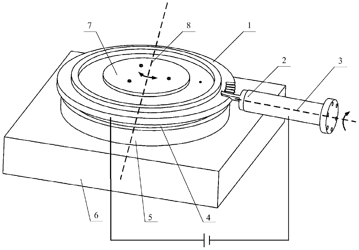
[0057] The technical solution of the present invention will be further described below in conjunction with the accompanying drawings.

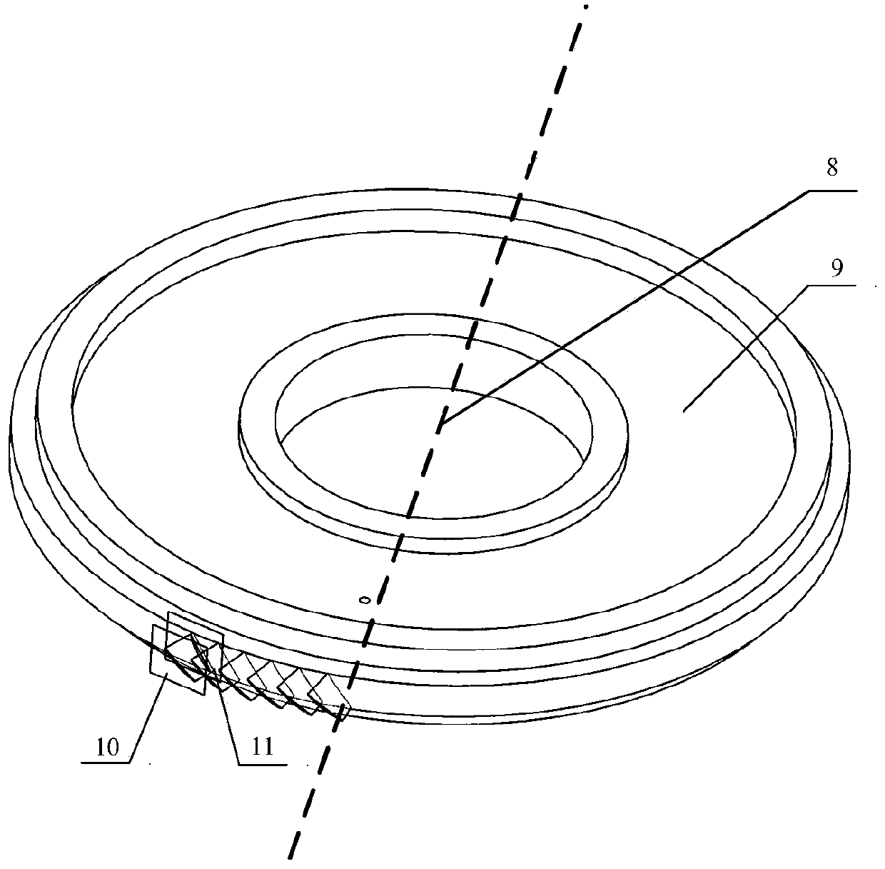
[0058] Such as figure 1 and as Figure 11 As shown, the electrolytic machining device of the present invention includes a whole plate blank 1, a tool cathode 2, a fixture disc 4, a turntable 5, a working platform 6, a pressing plate 7, an electrolytic machining fixture 36, a large gear 37, a pinion 38 and a motor 39. The whole plate blank 1 is connected with the fixture plate 4 by pins, the fixture plate 4 is connected with the turntable 5 by screws, the turntable 5 is located on the working platform 6, the pressure plate 7 is connected with the fixture plate 4 by screws, and the whole plate blank 1 is fastened. Among them, the pressure plate 7, the entire plate blank 1, the fixture plate 4, and the turntable 5 are arranged coaxially. Driven by the turntable 5, the pressure plate 7, the entire plate blank 1 and the fixture plate 4 rotate toge...


PUM


Abstract

The invention discloses a non-uniform-speed double-rotation variable-machining-blade cathode blisk electrolytic machining method. The method comprises the following steps that a rotating feeding shaftof a tool cathode is determined through simulation solution; the rotation angles and the rotation speeds of the tool cathode at different positions are determined through simulation solution, and themotion track of the tool cathode simulation is obtained; the rotation direction, the rotation angle and the rotation speed of a blisk blank is determined through simulation solution; a machining blade of the tool cathode is designed to be a variable-width machining blade; the tool cathode is driven to perform one-way variable-speed rotating radial feeding from the tool setting position along therotating feeding shaft according to the motion track of the simulation by taking the twisting direction of a blisk design model blade profile as the rotation direction; and the blisk blank is driven to cooperate with the variable-direction variable-speed rotation of the tool cathode around the central axis according to the rotation direction, the rotation speed and the rotation angle of simulationoptimization, and a blade lattice channel is formed on the blisk blank. According to the method, the electrolytically-formed blade lattice channel is uniform in allowance distribution and high in surface machining quality, and precise electrolytic machining of the blade lattice channel of the blisk can be realized.

Description

technical field [0001] The invention belongs to the technical field of electrolytic machining, and in particular relates to an electrolytic machining method for a non-uniform double-rotation variable machining blade cathode integral blisk. Background technique [0002] As the core component of the aerospace engine, the blisk has greatly improved the thrust-to-weight ratio and working efficiency of the aerospace engine. However, the blisk is widely used in some difficult-to-machine materials such as nickel-based superalloys and titanium alloys; Strict technical requirements such as precision and surface quality make the machining of the blisk very difficult. [0003] In the process of electrolytic machining, the tool electrode and the workpiece are not affected by the cutting force, so the electrolytic machining is not affected by the strength and hardness of the processed material, and the range of materials that can be processed is wide; and because there is no cutting forc...

Claims


Application Information

Patent Timeline
IPC IPC(8): B23H9/00B23H3/00
CPCB23H3/00B23H9/00
Inventor 徐正扬王璟朱荻
Owner NANJING UNIV OF AERONAUTICS & ASTRONAUTICS
Why Eureka
Try Eureka