Device for preventing burning and explosion of new energy automobile batteries caused by thermal runaway

A new energy vehicle, thermal runaway technology, used in battery/fuel cell control devices, battery temperature control, electric vehicles, etc., can solve problems such as battery short circuit, danger, inconvenience, etc., to prevent the generation of internal arcs in the battery, and protect life. The effect of property safety and simple production method

Pending Publication Date: 2019-12-24
赣州市惠丽生物科技有限公司
View PDF0 Cites 0 Cited by
  • Summary
  • Abstract
  • Description
  • Claims
  • Application Information

AI Technical Summary

Problems solved by technology

First, if a thermal runaway reaction occurs during charging and discharging, it may cause the battery to short-circuit and catch fire, or even explode.
Second, if extreme conditions such as collision, extrusion, or drop occur, the internal short circuit of the battery will be caused, which will also cause a dangerous situation.
2. The use of gas (air) as the heat transfer medium has

Method used


Image

  • Device for preventing burning and explosion of new energy automobile batteries caused by thermal runaway
  • Device for preventing burning and explosion of new energy automobile batteries caused by thermal runaway

Examples


Embodiment 1

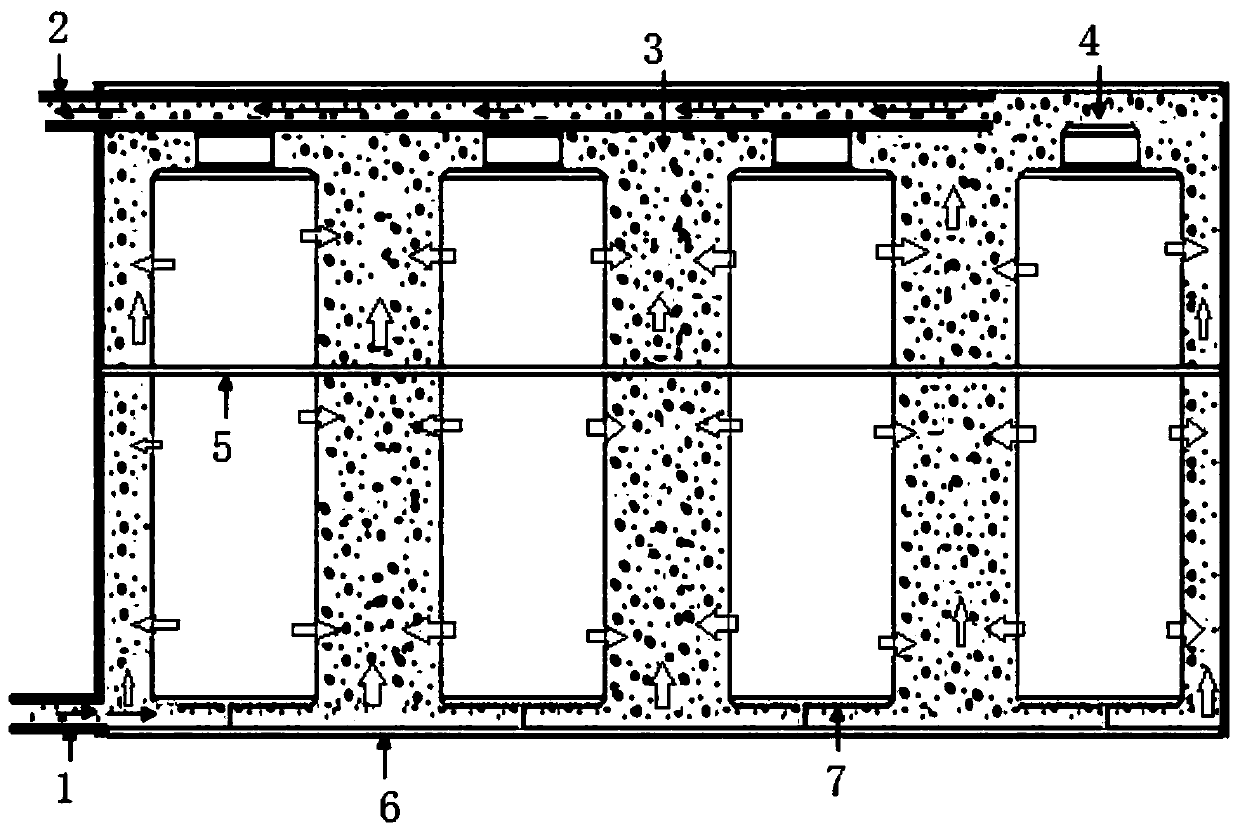
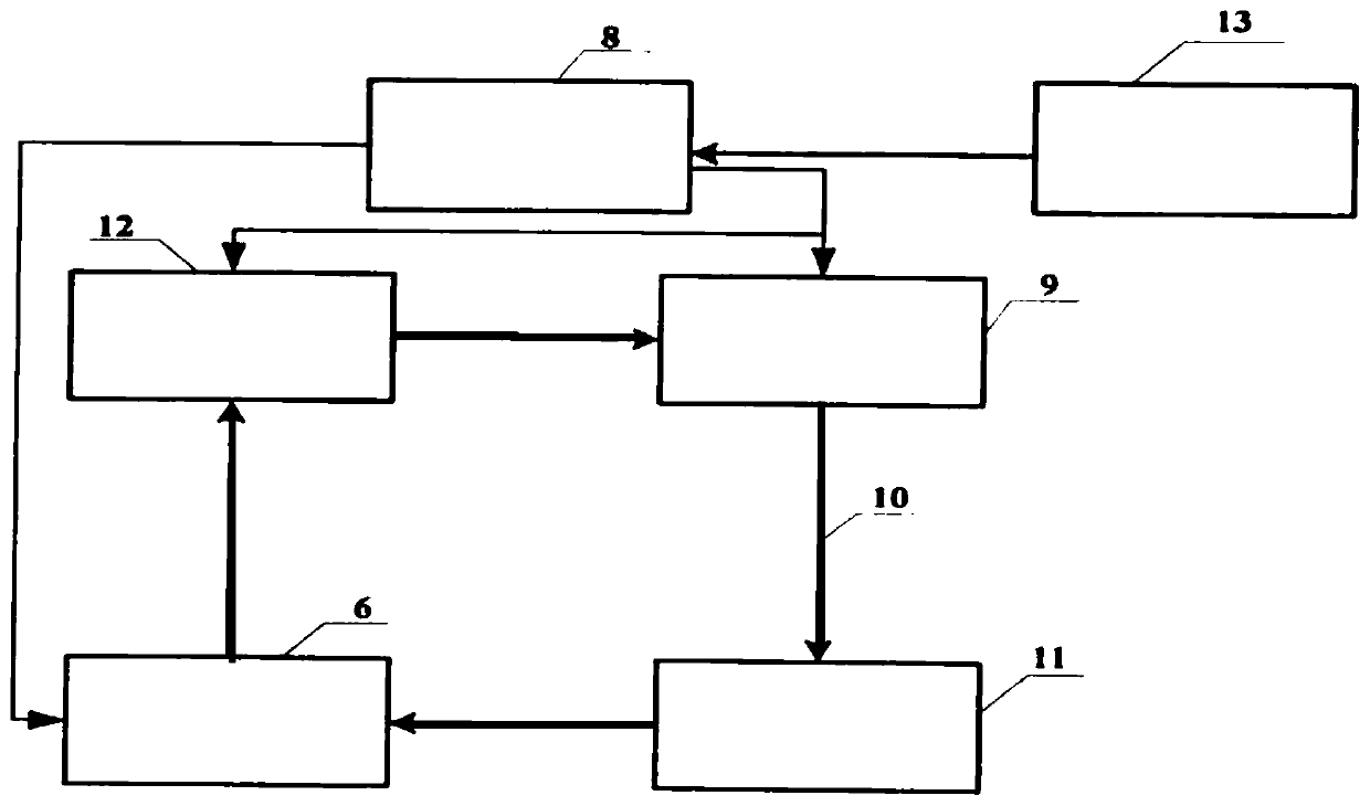
[0031] In this embodiment, the room temperature is 28 degrees, the equipment is 8w water pump, water tank, radiator 10w fan, temperature control unit, power supply is 12V / 2A adapter, 2500ml capacity stainless steel pot, 220V / 800W induction cooker, pipeline, and circulating fluid is 2000ml tap water. Assemble according to the steps of the above technical solution, the battery box is replaced by a stainless steel pot with a capacity of 2500ml, and the circulating fluid is replaced by tap water.

[0032] 1.0. Take 2000ml of tap water, put it into a stainless steel pot and cover it, turn on the induction cooker to heat, start the liquid cooling system, set the radiator fan to start at 40 degrees, and it takes 12 minutes and 30 seconds to heat the water temperature from 36 degrees to 74 degrees. 1.1. It takes 7 minutes and 30 seconds to heat the water temperature from 36 degrees to 74 degrees without starting the liquid cooling system. 2.0. Start the liquid cooling system, set the ...

Embodiment 2

[0034] In this embodiment, the room temperature is 28 degrees, the equipment is 8w water pump, water tank, radiator 10w fan, temperature control unit, power supply is 12V / 2A adapter, 2500ml capacity stainless steel pot, 220V / 800W induction cooker, pipeline, circulating fluid is 2000ml10# square shed Oil. Assemble according to the steps of the above technical scheme, replace the battery box with a stainless steel pot with a capacity of 2500ml, and use 10# square shed oil for the circulating fluid.

[0035] 1.0. Take 2000ml 10# square shed oil and pour it into the stainless steel pot and cover it, turn on the induction cooker to heat, start the liquid cooling system, set the radiator fan to start at 40 degrees, and it takes 6 minutes to heat the oil temperature from 36 degrees to 74 degrees . 1.1. It takes 3 minutes and 40 seconds to heat the oil temperature from 36 degrees to 74 degrees without starting the liquid cooling system. 2.0. Start the liquid cooling system and set t...


PUM


Abstract

The invention discloses a device for preventing burning and explosion of new energy automobile batteries caused by thermal runaway, and relates to a battery device technology. The device comprises a temperature control unit and a battery box body. An output conduit is mounted at the upper end of one side of the battery box body, and an input conduit is mounted at the lower end. The output conduitof the battery box body is communicated with a radiator through a pipeline, the radiator is communicated with a water pump through a pipeline, the water pump is communicated with a water tank througha pipeline, and the water tank is communicated with the input conduit of the battery box body through a pipeline. The temperature control unit is electrically connected with the battery box body, thewater pump and a radiator fan respectively. The battery box body is filled with circulating liquid. The device for preventing burning and explosion of new energy automobile batteries caused by thermalrunaway provided by the invention enables automobile batteries to have the functions of temperature control, insulation, flame retardancy and prevention of burning and explosion caused by thermal runaway.

Description

technical field [0001] The invention relates to the technical field of battery devices, in particular to a device for preventing thermal runaway explosion of batteries of new energy vehicles. Background technique [0002] Pure electric vehicles are currently the only choice for new energy vehicles, and they are also an important measure at home and abroad to solve vehicle pollution, promote low-carbon travel, and promote green environmental protection. The so-called pure electric vehicles use batteries as power sources and are driven by electric motors. The battery is its heart and key, as well as its life and value. For many people, new energy vehicles are a recently emerging type of vehicle. Due to the impact of the environment, our current traditional fuel vehicles are greatly restricted, so the promotion of new energy vehicles is becoming more and more widespread. The manufacturing time of new energy vehicles is very short, so there will definitely be deficiencies in t...

Claims


Application Information

Patent Timeline
IPC IPC(8): H01M10/42H01M10/48H01M10/613H01M10/625H01M10/63H01M10/6563H01M10/6567B60L58/26
CPCB60L58/26H01M10/425H01M10/4285H01M10/484H01M10/613H01M10/625H01M10/63H01M10/6563H01M10/6567H01M2010/4271Y02E60/10Y02T10/70
Inventor 张宸赖昭君叶光斌
Owner 赣州市惠丽生物科技有限公司
Why Eureka
Try Eureka