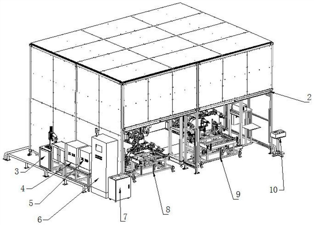
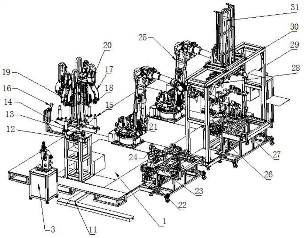
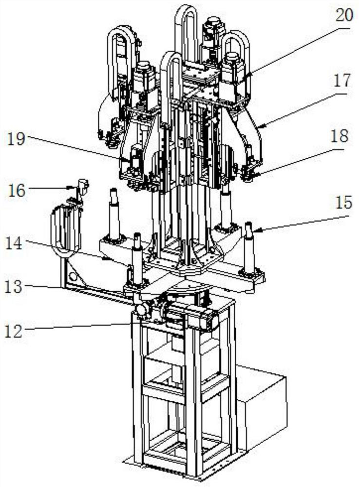
A robot ultrasonic punching, sticking bracket, bridge approach cutting integrated machine

A robot and ultrasonic technology, applied in the direction of metal processing, etc., can solve problems such as the inability to realize bumper production, huge investment in plant equipment, and large plant area, so as to save time for production change and debugging, save investment in equipment assets, and save The effect of footprint

Inactive Publication Date: 2021-04-09
广州亚琛自动化控制设备有限公司
View PDF5 Cites 1 Cited by
  • Summary
  • Abstract
  • Description
  • Claims
  • Application Information

AI Technical Summary

Problems solved by technology

[0003] The first-generation equipment, each car-shaped front and rear bumper is equipped with a punching machine, a bracket sticking equipment, and an approach bridge cutting equipment. The factory covers a large area and has many operators. When a model is eliminated, the equipment will be scrapped. When the production capacity is insufficient and there are many products, the investment in plant and equipment is huge. The second-generation equipment combines punching and sticking brackets on the basis of the first generation. One equipment is equipped for the front and rear bumpers, and an approach bridge cutting equipment is equipped. , the plant area and labor cost have been improved, but it also requires one model and one equipment, which requires a large investment and equipment to be eliminated when the model is eliminated. The third-generation equipment uses robots, ultrasonic punching, sticking brackets as a whole, and approach bridge cutting. It is a self-produced equipment with a large investment; when changing the model, it is only necessary to replace the punching jig and bracket jig, punch and die. Similarly, after punching and bracketing, it must be manually moved to the approach bridge for cutting; It is impossible to realize the production of multiple hole diameters on a bumper,

Method used


Image

  • A robot ultrasonic punching, sticking bracket, bridge approach cutting integrated machine
  • A robot ultrasonic punching, sticking bracket, bridge approach cutting integrated machine
  • A robot ultrasonic punching, sticking bracket, bridge approach cutting integrated machine

Examples


Embodiment Construction

[0021] In order to make the technical means, creative features, goals and effects achieved by the present invention easy to understand, the present invention will be further described below in conjunction with specific embodiments.

[0022] In the description of the present invention, it should be noted that the terms "upper", "lower", "inner", "outer", "front end", "rear end", "both ends", "one end", "another end" The orientation or positional relationship indicated by etc. is based on the orientation or positional relationship shown in the drawings, and is only for the convenience of describing the present invention and simplifying the description, rather than indicating or implying that the referred device or element must have a specific orientation, use a specific Azimuth configuration and operation, therefore, should not be construed as limiting the invention. In addition, the terms "first" and "second" are used for descriptive purposes only, and should not be understood ...


PUM


Abstract

The invention discloses a robotic ultrasonic punching, bracket sticking and bridge approach cutting integrated machine, comprising a mounting support, a dustproof cover is fixedly installed on the top of the mounting support, and a tensile testing machine is fixedly installed on the top of the mounting support A cutting robot control cabinet is fixedly installed on the top of the installation support, a punching robot control cabinet is fixed on the top of the installation support, and a central control system is fixed on the top of the installation support. The robot ultrasonic punching, bracket sticking and bridge approach cutting integrated machine of the present invention reduces asset costs, saves the time for punch and die replacement and debugging, and only needs one button to complete the production change, and only needs to be pressed on the operation cabinet before production. Models, the equipment automatically recognizes all jigs, punches and dies, and automatically turns the four-station punching machine to the required station. When all matching is in line with the preparation and the indicator light is on, production can begin, avoiding waste, Production of defective products.

Description

technical field [0001] The invention relates to the field of automobile processing equipment, in particular to an integrated machine for robot ultrasonic punching, bracket sticking and bridge approach cutting. Background technique [0002] There are bumpers on the car. Now with the continuous development and innovation of technology, the car will be equipped with radar detection function, and the radar is installed on the front and rear bumpers of the car, so the installation hole must be processed when the bumper is produced. Because the bumper The cost of injection mold is relatively high, and it is not possible to have a set of molds for each specification. Therefore, radar holes are not injected during injection molding. It needs to be processed in later production. From manual opening-first generation punching machine-second generation punching machine-third generation punching machine. [0003] The first-generation equipment, each car-shaped front and rear bumper is e...

Claims


Application Information

Patent Timeline
Patent Type & Authority Patents(China)
IPC IPC(8): B26F1/02B26D7/08B29C65/48B26D9/00
CPCB26D7/086B26D9/00B26F1/02B29C65/48B29C66/80
Inventor 郭雨何盛斌
Owner 广州亚琛自动化控制设备有限公司
Why Eureka
Try Eureka